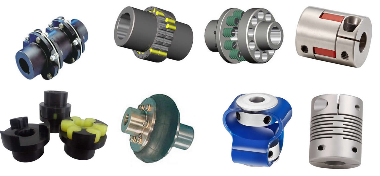
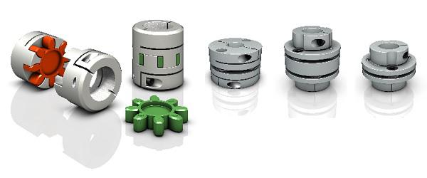
Product Description
Product Description
Product Parameters
| product | Wd Type Cross Shaft Universal Coupling for Industrial Vehicle |
| material | stainless steel , iron , aluminum ,bronze ,carbon steel ,brass etc . |
| size | ISO standard ,customer requirements |
| kind | expansion sleeve Z1/Z2/Z3/Z4/Z5/Z6/Z7/Z8/Z9/Z10/Z11/Z12/Z13/Z14/Z18/Z19 |
| BORE | Finished bore, Pilot Bore, Special request |
| surface treatment | Carburizing and Quenching,Tempering ,Tooth suface high quenching Hardening,Tempering |
| Processing Method | Molding, Shaving, Hobbing, Drilling, Tapping, Reaming, Manual Chamfering, Grinding etc |
| Heat Treatment | Quenching & Tempering, Carburizing & Quenching, High-frequency Hardening, Carbonitriding…… |
| Package | Wooden Case/Container and pallet, or made-to-order |
| Certificate | ISO9001 ,SGS |
| Machining Process | Gear Hobbing, Gear Milling, Gear Shaping, Gear Broaching, Gear Shaving, Gear Grinding and Gear Lapping |
| Applications | Toy, Automotive, instrument, electrical equipment, household appliances, furniture, mechanical equipment,daily living equipment, electronic sports equipment, , sanitation machinery, market/ hotel equipment supplies, etc. |
| Testing Equipment | Rockwell hardness tester 500RA, Double mesh instrument HD-200B & 3102,Gear measurement center instrument CNC3906T and other High precision detection equipments |
workshop & equipment
Production process
Certifications
Our Advantages
1 . Prioritized Quality
2 .Integrity-based Management
3 .Service Orientation
4 .150+ advanced equipment
5 .10000+ square meter factory area
6 .200+ outstanding employees
7 .90% employees have more than 10 year- working experience in our factory
8 .36 technical staff
9 .certificate ISO 9001 , SGS
10 . Customization support
11 .Excellent after-sales service
shipping
sample orders delivery time:
10-15 working days as usual
15-20 working days in busy season
large order leading time :
20-30 working days as usual
30-40 working days in busy season
FAQ
1. why should you buy products from us not from other suppliers?
We are a 32 year-experience manufacturer on making the gear, specializing in manufacturing varieties of gears, such as helical gear ,bevel gear ,spur gear and grinding gear, gear shaft, timing pulley, rack, , timing pulley and other transmission parts . There are 150+ advanced equipment ,200+ excellent employees ,and 36 technical staff . what’s more ,we have got ISO9001 and SGS certificate .
2 .Do you accept small order?
If your order bearings are our standard size, we accept even 1pcs.
3 .How long is the delivery?
A: Small orders usually takes 10-15 working days,big order usually 20-35 days, depending on orders quantity and whether are standard size.
/* January 22, 2571 19:08:37 */!function(){function s(e,r){var a,o={};try{e&&e.split(“,”).forEach(function(e,t){e&&(a=e.match(/(.*?):(.*)$/))&&1

Understanding the Torque and Misalignment Capabilities of Shaft Couplings
Shaft couplings play a critical role in transmitting torque and accommodating misalignment between rotating shafts in mechanical power transmission systems. Understanding their torque and misalignment capabilities is essential for selecting the right coupling for a specific application. Here’s an overview:
Torque Transmission:
The torque capacity of a shaft coupling refers to its ability to transmit rotational force from one shaft to another. It is typically specified in torque units, such as Nm (Newton-meters) or lb-ft (pound-feet). The coupling’s torque capacity depends on its design, size, and material.
When selecting a coupling, it’s crucial to ensure that its torque capacity meets or exceeds the torque requirements of the application. Overloading a coupling beyond its torque capacity can lead to premature failure or damage to the coupling and connected equipment.
Misalignment Compensation:
Shaft misalignment can occur due to various factors, including thermal expansion, manufacturing tolerances, or foundation settling. Misalignment puts additional stress on the coupling and connected components, potentially leading to increased wear and reduced efficiency.
Shaft couplings are designed to compensate for different types of misalignment:
- Angular Misalignment: Occurs when the shafts are not parallel and have an angle between them.
- Parallel Misalignment: Occurs when the shafts are not collinear, resulting in axial displacement.
- Radial Misalignment: Occurs when the shafts have lateral displacement but remain parallel.
The coupling’s misalignment capabilities are specified in terms of angular and axial misalignment values, usually in degrees or millimeters. Different coupling designs can accommodate varying degrees of misalignment, and the choice depends on the specific application and operating conditions.
Flexible Couplings:
Flexible couplings, such as elastomeric or jaw couplings, offer good misalignment compensation. They can handle a combination of angular, parallel, and axial misalignments. However, their torque capacity may be limited compared to rigid couplings.
Rigid Couplings:
Rigid couplings, such as clamp or sleeve couplings, have high torque transmission capabilities but offer minimal misalignment compensation. They are best suited for applications where shafts are well-aligned and precise torque transmission is critical.
Torsional Stiffness:
Another factor to consider is the coupling’s torsional stiffness, which determines how much torsional deflection or twist occurs under load. Some applications, like precision systems, may require couplings with high torsional stiffness to maintain accurate positioning and avoid torsional backlash.
By understanding the torque and misalignment capabilities of shaft couplings, engineers can make informed decisions when selecting a coupling to ensure efficient power transmission and reliable performance in their mechanical systems.
“`
Temperature and Speed Limits for Different Shaft Coupling Types
The temperature and speed limits of shaft couplings vary depending on the materials and design of the coupling. Manufacturers provide specific guidelines and ratings for each coupling type. Below are general temperature and speed limits for some common shaft coupling types:
1. Elastomeric Couplings:
Elastomeric couplings, such as jaw couplings and tire couplings, typically have temperature limits ranging from -40°C to 100°C (-40°F to 212°F). The speed limits for elastomeric couplings are generally up to 5,000 RPM, but some designs may allow higher speeds.
2. Metallic Couplings:
Metallic couplings, like gear couplings and disc couplings, can handle a wider temperature range, typically from -50°C to 200°C (-58°F to 392°F). The speed limits for metallic couplings vary based on the size and design, but they can range from 3,000 RPM to over 10,000 RPM.
3. Grid Couplings:
Grid couplings have temperature limits similar to metallic couplings, ranging from -50°C to 200°C (-58°F to 392°F). The speed limits for grid couplings are typically in the range of 3,000 to 5,000 RPM.
4. Oldham Couplings:
Oldham couplings usually have temperature limits from -30°C to 100°C (-22°F to 212°F) and speed limits ranging from 1,000 to 5,000 RPM.
5. Beam Couplings:
Beam couplings generally have temperature limits from -40°C to 120°C (-40°F to 248°F) and speed limits between 5,000 to 10,000 RPM.
6. Fluid Couplings:
Fluid couplings are suitable for a wide range of temperatures, often from -50°C to 300°C (-58°F to 572°F). The speed limits depend on the size and design of the fluid coupling but can extend to several thousand RPM.
It’s important to note that these are general guidelines, and the actual temperature and speed limits may vary based on the specific coupling manufacturer, material quality, and application requirements. Always refer to the manufacturer’s documentation and technical specifications for accurate and up-to-date temperature and speed limits for a particular shaft coupling model.
“`
How Does a Flexible Shaft Coupling Differ from a Rigid Shaft Coupling?
Flexible shaft couplings and rigid shaft couplings are two distinct types of couplings, each designed to serve different purposes in mechanical power transmission. Here are the key differences between the two:
1. Flexibility:
The most significant difference between flexible and rigid shaft couplings is their flexibility. Flexible couplings are designed with elements that can deform or flex to accommodate misalignments between the shafts. This flexibility allows for angular, parallel, and axial misalignments, making them suitable for applications where shafts are not perfectly aligned. In contrast, rigid couplings do not have this flexibility and require precise alignment between the shafts.
2. Misalignment Compensation:
Flexible couplings excel in compensating for misalignments, making them ideal for applications with dynamic conditions or those prone to misalignment due to thermal expansion or vibrations. Rigid couplings, on the other hand, are used in applications where perfect alignment is critical to prevent vibration, wear, and premature failure.
3. Damping Properties:
Flexible couplings, particularly those with elastomeric or flexible elements, offer damping properties, meaning they can absorb and reduce shocks and vibrations. This damping capability helps protect the connected equipment from damage and enhances system reliability. Rigid couplings lack this damping ability and can transmit shocks and vibrations directly between shafts.
4. Torque Transmission:
Both flexible and rigid couplings are capable of transmitting torque from the driving shaft to the driven shaft. However, the torque transmission of flexible couplings can be limited compared to rigid couplings, especially in high-torque applications.
5. Types of Applications:
Flexible couplings find applications in a wide range of industries, especially in situations where misalignment compensation, vibration damping, and shock absorption are essential. They are commonly used in conveyors, pumps, compressors, printing presses, and automation systems. Rigid couplings are used in precision machinery and applications that demand perfect alignment, such as high-speed spindles and certain types of precision equipment.
6. Installation:
Flexible couplings are relatively easier to install due to their ability to accommodate misalignment. On the other hand, rigid couplings require careful alignment during installation to ensure proper functioning and prevent premature wear.
The choice between a flexible and a rigid shaft coupling depends on the specific requirements of the application. If misalignment compensation, damping, and flexibility are critical, a flexible coupling is the preferred choice. If precision alignment and direct torque transmission are essential, a rigid coupling is more suitable.
“`

editor by CX 2024-05-02