Product Description
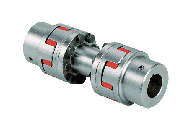
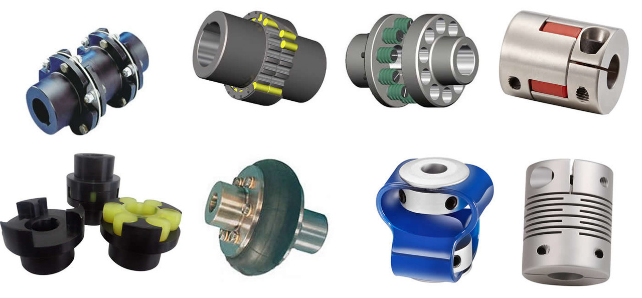
Flexible flex Fluid Chain Jaw flange Gear Rigid Spacer PIN HRC MH NM universal Fenaflex Oldham spline clamp tyre grid hydraulic servo motor shaft Coupling
Product Description
The function of Shaft coupling:
1. Shafts for connecting separately manufactured units such as motors and generators.
2. If any axis is misaligned.
3. Provides mechanical flexibility.
4. Absorb the transmission of impact load.
5. Prevent overload
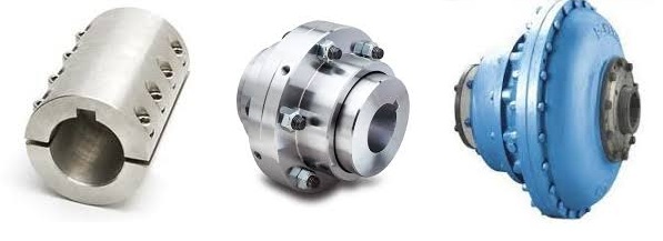
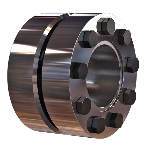
We can provide the following couplings.
| Rigid coupling | Flange coupling | Oldham coupling |
| Sleeve or muff coupling | Gear coupling | Bellow coupling |
| Split muff coupling | Flexible coupling | Fluid coupling |
| Clamp or split-muff or compression coupling | Universal coupling | Variable speed coupling |
| Bushed pin-type coupling | Diaphragm coupling | Constant speed coupling |
Company Profile
We are an industrial company specializing in the production of couplings. It has 3 branches: steel casting, forging, and heat treatment. Main products: cross shaft universal coupling, drum gear coupling, non-metallic elastic element coupling, rigid coupling, etc.
The company mainly produces the industry standard JB3241-91 swap JB5513-91 swc. JB3242-93 swz series universal coupling with spider type. It can also design and produce various non-standard universal couplings, other couplings, and mechanical products for users according to special requirements. Currently, the products are mainly sold to major steel companies at home and abroad, the metallurgical steel rolling industry, and leading engine manufacturers, with an annual production capacity of more than 7000 sets.
The company’s quality policy is “quality for survival, variety for development.” In August 2000, the national quality system certification authority audited that its quality assurance system met the requirements of GB/T19002-1994 IDT ISO9002:1994 and obtained the quality system certification certificate with the registration number 0900B5711. It is the first enterprise in the coupling production industry in HangZhou City that passed the ISO9002 quality and constitution certification.
The company pursues the business purpose of “reliable quality, the supremacy of reputation, commitment to business and customer satisfaction” and welcomes customers at home and abroad to choose our products.
At the same time, the company has established long-term cooperative relations with many enterprises and warmly welcomes friends from all walks of life to visit, investigate and negotiate business!
How to use the coupling safely
The coupling is an intermediate connecting part of each motion mechanism, which directly impacts the regular operation of each motion mechanism. Therefore, attention must be paid to:
1. The coupling is not allowed to have more than the specified axis deflection and radial displacement so as not to affect its transmission performance.
2. The bolts of the LINS coupling shall not be loose or damaged.
3. Gear coupling and cross slide coupling shall be lubricated regularly, and lubricating grease shall be added every 2-3 months to avoid severe wear of gear teeth and serious consequences.
4. The tooth width contact length of gear coupling shall not be less than 70%; Its axial displacement shall not be more significant than 5mm
5. The coupling is not allowed to have cracks. If there are cracks, it needs to be replaced (they can be knocked with a small hammer and judged according to the sound).
6. The keys of LINS coupling shall be closely matched and shall not be loosened.
7. The tooth thickness of the gear coupling is worn. When the lifting mechanism exceeds 15% of the original tooth thickness, the operating mechanism exceeds 25%, and the broken tooth is also scrapped.
8. If the elastic ring of the pin coupling and the sealing ring of the gear coupling is damaged or aged, they should be replaced in time.
Certifications
Packaging & Shipping
/* January 22, 2571 19:08:37 */!function(){function s(e,r){var a,o={};try{e&&e.split(“,”).forEach(function(e,t){e&&(a=e.match(/(.*?):(.*)$/))&&1
Is It Possible to Replace a Shaft Coupling Without Professional Assistance?
Yes, it is possible to replace a shaft coupling without professional assistance, especially if you have some mechanical knowledge and the necessary tools. However, the ease of replacement can vary depending on the type of coupling and the complexity of the equipment. Here are some general steps to guide you through the process:
1. Safety First:
Before starting any work, ensure that the equipment is turned off and disconnected from the power source. Use appropriate personal protective equipment (PPE) to protect yourself from potential hazards.
2. Assess the Coupling Type:
Different types of couplings may have specific installation and removal methods. Identify the type of coupling you need to replace, and consult the manufacturer’s documentation or online resources for guidance.
3. Gather Tools and Materials:
Collect the necessary tools, such as wrenches, sockets, and a puller (if required), to safely remove the old coupling. Have the new coupling ready for installation, ensuring it matches the specifications of the old one.
4. Disassembly:
If your coupling is a split or clamp-style coupling, you may be able to replace it without fully disassembling the connected equipment. Otherwise, you may need to remove other components to access the coupling.
5. Remove Fasteners:
Loosen and remove any fasteners, such as set screws, that secure the old coupling to the shafts. Take care not to damage the shafts during this process.
6. Extraction:
If the old coupling is tightly fitted on the shafts, you may need to use a coupling puller or other appropriate extraction tools to safely remove it.
7. Clean and Inspect:
After removing the old coupling, clean the shaft ends and inspect them for any signs of damage or wear. Also, check for any misalignment issues that may have contributed to the old coupling’s failure.
8. Install New Coupling:
Follow the manufacturer’s instructions for installing the new coupling. Apply appropriate lubrication and ensure the coupling is correctly aligned with the shafts.
9. Fasten Securely:
Tighten the fasteners to the manufacturer’s recommended torque values to securely attach the new coupling to the shafts.
10. Test Run:
After installation, perform a test run of the equipment to ensure the new coupling operates smoothly and without issues.
While it is possible to replace a shaft coupling without professional assistance, keep in mind that some couplings and equipment may require specialized knowledge and tools for safe and proper replacement. If you are uncertain about the process or encounter any difficulties, it is advisable to seek help from a qualified professional or technician to avoid potential damage to the equipment or injury to yourself.
“`
Explaining the Concept of Backlash and How It Affects Shaft Coupling Performance
Backlash is the angular movement or play between the mating components of a mechanical system when the direction of motion is reversed. In the context of shaft couplings, backlash refers to the free rotational movement between the connected shafts before the coupling transmits torque from one shaft to the other.
Backlash occurs in certain coupling designs that have features allowing relative movement between the coupling’s mating parts. Common coupling types that may exhibit some degree of backlash include elastomeric couplings (such as jaw couplings), gear couplings, and Oldham couplings.
How Backlash Affects Shaft Coupling Performance:
1. Loss of Precision: In applications requiring precise motion control, backlash can lead to inaccuracies and reduced positional accuracy. For example, in CNC machines or robotics, any rotational play due to backlash can result in positioning errors and decreased machining or movement precision.
2. Reversal Impact: When a reversing load is applied to a coupling, the presence of backlash can lead to a brief period of rotational play before the coupling re-engages, causing a momentary jolt or impact. This impact can lead to increased stress on the coupling and connected components, potentially reducing their lifespan.
3. Dynamic Response: Backlash can affect the dynamic response of the mechanical system. In systems requiring rapid acceleration or deceleration, the initial play due to backlash may create a delay in torque transmission, affecting the system’s responsiveness.
4. Noise and Vibration: Backlash can cause noise and vibration in the system, leading to increased wear and potential fatigue failure of components.
5. Misalignment Compensation: In some flexible coupling designs, a certain amount of backlash is intentionally incorporated to allow for misalignment compensation. While this is a beneficial feature, excessive backlash can compromise the coupling’s performance.
Minimizing Backlash:
Manufacturers often design couplings with specific features to minimize backlash. For instance, some gear couplings employ crowned gear teeth to reduce clearance, while elastomeric couplings may have preloaded elastomeric elements. Precision couplings like zero-backlash or torsionally rigid couplings are engineered to eliminate or minimize backlash for applications requiring high accuracy and responsiveness.
When selecting a coupling, it’s essential to consider the application’s specific requirements regarding precision, speed, reversing loads, and misalignment compensation, as these factors will determine the acceptable level of backlash for optimal performance.
“`
Best Practices for Installing a Shaft Coupling for Optimal Performance
Proper installation of a shaft coupling is crucial for ensuring optimal performance and preventing premature wear or failure. Follow these best practices to install a shaft coupling correctly:
1. Shaft Alignment:
Ensure that both the driving and driven shafts are properly aligned before installing the coupling. Misalignment can lead to increased stress on the coupling and other connected components, reducing efficiency and causing premature wear. Use alignment tools, such as dial indicators or laser alignment systems, to achieve accurate shaft alignment.
2. Cleanliness:
Before installation, clean the shaft ends and the coupling bore thoroughly. Remove any dirt, debris, or residue that could interfere with the coupling’s fit or cause misalignment.
3. Lubrication:
Apply the recommended lubricant to the coupling’s contact surfaces, such as the bore and shaft ends. Proper lubrication ensures smooth installation and reduces friction during operation.
4. Correct Fit:
Ensure that the coupling is the correct size and type for the application. Use couplings with the appropriate torque and speed ratings to match the equipment’s requirements.
5. Fastening:
Use the recommended fastening methods, such as set screws or keyways, to securely attach the coupling to the shafts. Make sure the fasteners are tightened to the manufacturer’s specifications to prevent loosening during operation.
6. Spacer or Adapter:
If required, use a spacer or adapter to properly position the coupling on the shafts and maintain the desired distance between the driving and driven components.
7. Avoid Shaft Damage:
Be careful during installation to avoid damaging the shaft ends, especially when using set screws or other fastening methods. Shaft damage can lead to stress concentrations and eventual failure.
8. Check Runout:
After installation, check the coupling’s runout using a dial indicator to ensure that it rotates smoothly and without wobbling. Excessive runout can indicate misalignment or improper fit.
9. Periodic Inspection:
Regularly inspect the coupling and its components for signs of wear, misalignment, or damage. Perform routine maintenance as recommended by the manufacturer to prevent issues from worsening over time.
10. Follow Manufacturer’s Guidelines:
Always follow the manufacturer’s installation instructions and guidelines. Different types of couplings may have specific installation requirements that need to be adhered to for optimal performance and safety.
By following these best practices, you can ensure that your shaft coupling is installed correctly, maximizing its efficiency and reliability in your mechanical power transmission system.
“`

editor by CX 2024-04-11
China Custom Flexible Flex Fluid Chain Jaw Flange Gear Rigid Spacer Pin HRC Mh Nm Universal Fenaflex Oldham Spline Clamp Tyre Grid Hydraulic Servo Motor Shaft Coupling
Product Description
Flexible flex Fluid Chain Jaw flange Gear Rigid Spacer PIN HRC MH NM universal Fenaflex Oldham spline clamp tyre grid hydraulic servo motor shaft Coupling
Product Description
The function of Shaft coupling:
1. Shafts for connecting separately manufactured units such as motors and generators.
2. If any axis is misaligned.
3. Provides mechanical flexibility.
4. Absorb the transmission of impact load.
5. Prevent overload
We can provide the following couplings.
| Rigid coupling | Flange coupling | Oldham coupling |
| Sleeve or muff coupling | Gear coupling | Bellow coupling |
| Split muff coupling | Flexible coupling | Fluid coupling |
| Clamp or split-muff or compression coupling | Universal coupling | Variable speed coupling |
| Bushed pin-type coupling | Diaphragm coupling | Constant speed coupling |
Company Profile
We are an industrial company specializing in the production of couplings. It has 3 branches: steel casting, forging, and heat treatment. Main products: cross shaft universal coupling, drum gear coupling, non-metallic elastic element coupling, rigid coupling, etc.
The company mainly produces the industry standard JB3241-91 swap JB5513-91 swc. JB3242-93 swz series universal coupling with spider type. It can also design and produce various non-standard universal couplings, other couplings, and mechanical products for users according to special requirements. Currently, the products are mainly sold to major steel companies at home and abroad, the metallurgical steel rolling industry, and leading engine manufacturers, with an annual production capacity of more than 7000 sets.
The company’s quality policy is “quality for survival, variety for development.” In August 2000, the national quality system certification authority audited that its quality assurance system met the requirements of GB/T19002-1994 IDT ISO9002:1994 and obtained the quality system certification certificate with the registration number 0900B5711. It is the first enterprise in the coupling production industry in HangZhou City that passed the ISO9002 quality and constitution certification.
The company pursues the business purpose of “reliable quality, the supremacy of reputation, commitment to business and customer satisfaction” and welcomes customers at home and abroad to choose our products.
At the same time, the company has established long-term cooperative relations with many enterprises and warmly welcomes friends from all walks of life to visit, investigate and negotiate business!
How to use the coupling safely
The coupling is an intermediate connecting part of each motion mechanism, which directly impacts the regular operation of each motion mechanism. Therefore, attention must be paid to:
1. The coupling is not allowed to have more than the specified axis deflection and radial displacement so as not to affect its transmission performance.
2. The bolts of the LINS coupling shall not be loose or damaged.
3. Gear coupling and cross slide coupling shall be lubricated regularly, and lubricating grease shall be added every 2-3 months to avoid severe wear of gear teeth and serious consequences.
4. The tooth width contact length of gear coupling shall not be less than 70%; Its axial displacement shall not be more significant than 5mm
5. The coupling is not allowed to have cracks. If there are cracks, it needs to be replaced (they can be knocked with a small hammer and judged according to the sound).
6. The keys of LINS coupling shall be closely matched and shall not be loosened.
7. The tooth thickness of the gear coupling is worn. When the lifting mechanism exceeds 15% of the original tooth thickness, the operating mechanism exceeds 25%, and the broken tooth is also scrapped.
8. If the elastic ring of the pin coupling and the sealing ring of the gear coupling is damaged or aged, they should be replaced in time.
Certifications
Packaging & Shipping
/* January 22, 2571 19:08:37 */!function(){function s(e,r){var a,o={};try{e&&e.split(“,”).forEach(function(e,t){e&&(a=e.match(/(.*?):(.*)$/))&&1
Exploring the Use of Elastomeric Materials in Flexible Shaft Couplings
Elastomeric materials play a crucial role in the design and function of flexible shaft couplings. These materials, commonly known as elastomers, are rubber-like substances that exhibit high elasticity and flexibility. They are widely used in various types of flexible couplings due to their unique properties and benefits:
1. Damping and Vibration Absorption:
Elastomeric materials have excellent damping characteristics, meaning they can absorb and dissipate vibrations and shocks. This property is particularly useful in applications where vibration control is essential to protect sensitive equipment and improve overall system performance.
2. Misalignment Compensation:
Flexible shaft couplings with elastomeric elements can accommodate different types of misalignments, including angular, parallel, and radial misalignments. The elasticity of the material allows for limited movement between the shafts while still transmitting torque efficiently.
3. Torsional Flexibility:
Elastomers offer torsional flexibility, which allows them to twist and deform under torque loads. This feature helps to minimize torsional stresses and torsional backlash, making them suitable for applications requiring precise motion control.
4. Shock and Impact Resistance:
Due to their high resilience, elastomers can withstand sudden shocks and impacts without permanent deformation. This property makes them ideal for use in machinery subjected to varying loads or rapid changes in torque.
5. No Lubrication Requirement:
Elastomeric couplings are often maintenance-free because the elastomer material does not require additional lubrication. This reduces maintenance costs and simplifies the overall system upkeep.
6. Electric Isolation:
In certain applications, elastomeric materials can provide electrical isolation between the driving and driven components. This can help prevent the transmission of electrical currents or static charges through the coupling.
7. Corrosion Resistance:
Many elastomers used in couplings are resistant to corrosion, making them suitable for use in challenging environments where exposure to chemicals or moisture is a concern.
8. Easy Installation:
Elastomeric couplings are often designed for ease of installation and replacement. Their flexibility allows for simple and quick assembly onto the shafts without the need for special tools or complex procedures.
Given these advantages, elastomeric materials are popular choices for various flexible shaft couplings, including jaw couplings, tire couplings, and spider couplings. However, it is essential to select the right elastomer material based on the specific application requirements, such as temperature range, chemical compatibility, and torque capacity.
“`
Temperature and Speed Limits for Different Shaft Coupling Types
The temperature and speed limits of shaft couplings vary depending on the materials and design of the coupling. Manufacturers provide specific guidelines and ratings for each coupling type. Below are general temperature and speed limits for some common shaft coupling types:
1. Elastomeric Couplings:
Elastomeric couplings, such as jaw couplings and tire couplings, typically have temperature limits ranging from -40°C to 100°C (-40°F to 212°F). The speed limits for elastomeric couplings are generally up to 5,000 RPM, but some designs may allow higher speeds.
2. Metallic Couplings:
Metallic couplings, like gear couplings and disc couplings, can handle a wider temperature range, typically from -50°C to 200°C (-58°F to 392°F). The speed limits for metallic couplings vary based on the size and design, but they can range from 3,000 RPM to over 10,000 RPM.
3. Grid Couplings:
Grid couplings have temperature limits similar to metallic couplings, ranging from -50°C to 200°C (-58°F to 392°F). The speed limits for grid couplings are typically in the range of 3,000 to 5,000 RPM.
4. Oldham Couplings:
Oldham couplings usually have temperature limits from -30°C to 100°C (-22°F to 212°F) and speed limits ranging from 1,000 to 5,000 RPM.
5. Beam Couplings:
Beam couplings generally have temperature limits from -40°C to 120°C (-40°F to 248°F) and speed limits between 5,000 to 10,000 RPM.
6. Fluid Couplings:
Fluid couplings are suitable for a wide range of temperatures, often from -50°C to 300°C (-58°F to 572°F). The speed limits depend on the size and design of the fluid coupling but can extend to several thousand RPM.
It’s important to note that these are general guidelines, and the actual temperature and speed limits may vary based on the specific coupling manufacturer, material quality, and application requirements. Always refer to the manufacturer’s documentation and technical specifications for accurate and up-to-date temperature and speed limits for a particular shaft coupling model.
“`
Best Practices for Installing a Shaft Coupling for Optimal Performance
Proper installation of a shaft coupling is crucial for ensuring optimal performance and preventing premature wear or failure. Follow these best practices to install a shaft coupling correctly:
1. Shaft Alignment:
Ensure that both the driving and driven shafts are properly aligned before installing the coupling. Misalignment can lead to increased stress on the coupling and other connected components, reducing efficiency and causing premature wear. Use alignment tools, such as dial indicators or laser alignment systems, to achieve accurate shaft alignment.
2. Cleanliness:
Before installation, clean the shaft ends and the coupling bore thoroughly. Remove any dirt, debris, or residue that could interfere with the coupling’s fit or cause misalignment.
3. Lubrication:
Apply the recommended lubricant to the coupling’s contact surfaces, such as the bore and shaft ends. Proper lubrication ensures smooth installation and reduces friction during operation.
4. Correct Fit:
Ensure that the coupling is the correct size and type for the application. Use couplings with the appropriate torque and speed ratings to match the equipment’s requirements.
5. Fastening:
Use the recommended fastening methods, such as set screws or keyways, to securely attach the coupling to the shafts. Make sure the fasteners are tightened to the manufacturer’s specifications to prevent loosening during operation.
6. Spacer or Adapter:
If required, use a spacer or adapter to properly position the coupling on the shafts and maintain the desired distance between the driving and driven components.
7. Avoid Shaft Damage:
Be careful during installation to avoid damaging the shaft ends, especially when using set screws or other fastening methods. Shaft damage can lead to stress concentrations and eventual failure.
8. Check Runout:
After installation, check the coupling’s runout using a dial indicator to ensure that it rotates smoothly and without wobbling. Excessive runout can indicate misalignment or improper fit.
9. Periodic Inspection:
Regularly inspect the coupling and its components for signs of wear, misalignment, or damage. Perform routine maintenance as recommended by the manufacturer to prevent issues from worsening over time.
10. Follow Manufacturer’s Guidelines:
Always follow the manufacturer’s installation instructions and guidelines. Different types of couplings may have specific installation requirements that need to be adhered to for optimal performance and safety.
By following these best practices, you can ensure that your shaft coupling is installed correctly, maximizing its efficiency and reliability in your mechanical power transmission system.
“`

editor by CX 2024-03-07