Product Description
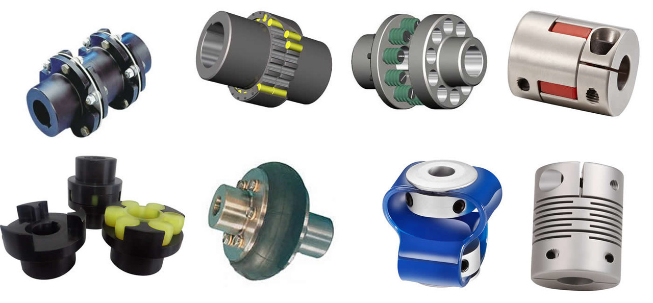
Flexible flex Fluid Chain Jaw flange Gear Rigid Spacer PIN HRC MH NM universal Fenaflex Oldham spline clamp tyre grid hydraulic servo motor shaft Coupling
Product Description
The function of Shaft coupling:
1. Shafts for connecting separately manufactured units such as motors and generators.
2. If any axis is misaligned.
3. Provides mechanical flexibility.
4. Absorb the transmission of impact load.
5. Prevent overload
We can provide the following couplings.
| Rigid coupling | Flange coupling | Oldham coupling |
| Sleeve or muff coupling | Gear coupling | Bellow coupling |
| Split muff coupling | Flexible coupling | Fluid coupling |
| Clamp or split-muff or compression coupling | Universal coupling | Variable speed coupling |
| Bushed pin-type coupling | Diaphragm coupling | Constant speed coupling |
Company Profile
We are an industrial company specializing in the production of couplings. It has 3 branches: steel casting, forging, and heat treatment. Main products: cross shaft universal coupling, drum gear coupling, non-metallic elastic element coupling, rigid coupling, etc.
The company mainly produces the industry standard JB3241-91 swap JB5513-91 swc. JB3242-93 swz series universal coupling with spider type. It can also design and produce various non-standard universal couplings, other couplings, and mechanical products for users according to special requirements. Currently, the products are mainly sold to major steel companies at home and abroad, the metallurgical steel rolling industry, and leading engine manufacturers, with an annual production capacity of more than 7000 sets.
The company’s quality policy is “quality for survival, variety for development.” In August 2000, the national quality system certification authority audited that its quality assurance system met the requirements of GB/T19002-1994 IDT ISO9002:1994 and obtained the quality system certification certificate with the registration number 0900B5711. It is the first enterprise in the coupling production industry in HangZhou City that passed the ISO9002 quality and constitution certification.
The company pursues the business purpose of “reliable quality, the supremacy of reputation, commitment to business and customer satisfaction” and welcomes customers at home and abroad to choose our products.
At the same time, the company has established long-term cooperative relations with many enterprises and warmly welcomes friends from all walks of life to visit, investigate and negotiate business!
How to use the coupling safely
The coupling is an intermediate connecting part of each motion mechanism, which directly impacts the regular operation of each motion mechanism. Therefore, attention must be paid to:
1. The coupling is not allowed to have more than the specified axis deflection and radial displacement so as not to affect its transmission performance.
2. The bolts of the LINS coupling shall not be loose or damaged.
3. Gear coupling and cross slide coupling shall be lubricated regularly, and lubricating grease shall be added every 2-3 months to avoid severe wear of gear teeth and serious consequences.
4. The tooth width contact length of gear coupling shall not be less than 70%; Its axial displacement shall not be more significant than 5mm
5. The coupling is not allowed to have cracks. If there are cracks, it needs to be replaced (they can be knocked with a small hammer and judged according to the sound).
6. The keys of LINS coupling shall be closely matched and shall not be loosened.
7. The tooth thickness of the gear coupling is worn. When the lifting mechanism exceeds 15% of the original tooth thickness, the operating mechanism exceeds 25%, and the broken tooth is also scrapped.
8. If the elastic ring of the pin coupling and the sealing ring of the gear coupling is damaged or aged, they should be replaced in time.
Certifications
Packaging & Shipping
/* January 22, 2571 19:08:37 */!function(){function s(e,r){var a,o={};try{e&&e.split(“,”).forEach(function(e,t){e&&(a=e.match(/(.*?):(.*)$/))&&1
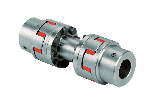
Is It Possible to Replace a Shaft Coupling Without Professional Assistance?
Yes, it is possible to replace a shaft coupling without professional assistance, especially if you have some mechanical knowledge and the necessary tools. However, the ease of replacement can vary depending on the type of coupling and the complexity of the equipment. Here are some general steps to guide you through the process:
1. Safety First:
Before starting any work, ensure that the equipment is turned off and disconnected from the power source. Use appropriate personal protective equipment (PPE) to protect yourself from potential hazards.
2. Assess the Coupling Type:
Different types of couplings may have specific installation and removal methods. Identify the type of coupling you need to replace, and consult the manufacturer’s documentation or online resources for guidance.
3. Gather Tools and Materials:
Collect the necessary tools, such as wrenches, sockets, and a puller (if required), to safely remove the old coupling. Have the new coupling ready for installation, ensuring it matches the specifications of the old one.
4. Disassembly:
If your coupling is a split or clamp-style coupling, you may be able to replace it without fully disassembling the connected equipment. Otherwise, you may need to remove other components to access the coupling.
5. Remove Fasteners:
Loosen and remove any fasteners, such as set screws, that secure the old coupling to the shafts. Take care not to damage the shafts during this process.
6. Extraction:
If the old coupling is tightly fitted on the shafts, you may need to use a coupling puller or other appropriate extraction tools to safely remove it.
7. Clean and Inspect:
After removing the old coupling, clean the shaft ends and inspect them for any signs of damage or wear. Also, check for any misalignment issues that may have contributed to the old coupling’s failure.
8. Install New Coupling:
Follow the manufacturer’s instructions for installing the new coupling. Apply appropriate lubrication and ensure the coupling is correctly aligned with the shafts.
9. Fasten Securely:
Tighten the fasteners to the manufacturer’s recommended torque values to securely attach the new coupling to the shafts.
10. Test Run:
After installation, perform a test run of the equipment to ensure the new coupling operates smoothly and without issues.
While it is possible to replace a shaft coupling without professional assistance, keep in mind that some couplings and equipment may require specialized knowledge and tools for safe and proper replacement. If you are uncertain about the process or encounter any difficulties, it is advisable to seek help from a qualified professional or technician to avoid potential damage to the equipment or injury to yourself.
“`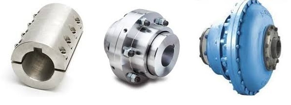
Explaining the Concept of Backlash and How It Affects Shaft Coupling Performance
Backlash is the angular movement or play between the mating components of a mechanical system when the direction of motion is reversed. In the context of shaft couplings, backlash refers to the free rotational movement between the connected shafts before the coupling transmits torque from one shaft to the other.
Backlash occurs in certain coupling designs that have features allowing relative movement between the coupling’s mating parts. Common coupling types that may exhibit some degree of backlash include elastomeric couplings (such as jaw couplings), gear couplings, and Oldham couplings.
How Backlash Affects Shaft Coupling Performance:
1. Loss of Precision: In applications requiring precise motion control, backlash can lead to inaccuracies and reduced positional accuracy. For example, in CNC machines or robotics, any rotational play due to backlash can result in positioning errors and decreased machining or movement precision.
2. Reversal Impact: When a reversing load is applied to a coupling, the presence of backlash can lead to a brief period of rotational play before the coupling re-engages, causing a momentary jolt or impact. This impact can lead to increased stress on the coupling and connected components, potentially reducing their lifespan.
3. Dynamic Response: Backlash can affect the dynamic response of the mechanical system. In systems requiring rapid acceleration or deceleration, the initial play due to backlash may create a delay in torque transmission, affecting the system’s responsiveness.
4. Noise and Vibration: Backlash can cause noise and vibration in the system, leading to increased wear and potential fatigue failure of components.
5. Misalignment Compensation: In some flexible coupling designs, a certain amount of backlash is intentionally incorporated to allow for misalignment compensation. While this is a beneficial feature, excessive backlash can compromise the coupling’s performance.
Minimizing Backlash:
Manufacturers often design couplings with specific features to minimize backlash. For instance, some gear couplings employ crowned gear teeth to reduce clearance, while elastomeric couplings may have preloaded elastomeric elements. Precision couplings like zero-backlash or torsionally rigid couplings are engineered to eliminate or minimize backlash for applications requiring high accuracy and responsiveness.
When selecting a coupling, it’s essential to consider the application’s specific requirements regarding precision, speed, reversing loads, and misalignment compensation, as these factors will determine the acceptable level of backlash for optimal performance.
“`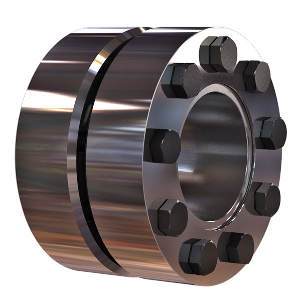
Best Practices for Installing a Shaft Coupling for Optimal Performance
Proper installation of a shaft coupling is crucial for ensuring optimal performance and preventing premature wear or failure. Follow these best practices to install a shaft coupling correctly:
1. Shaft Alignment:
Ensure that both the driving and driven shafts are properly aligned before installing the coupling. Misalignment can lead to increased stress on the coupling and other connected components, reducing efficiency and causing premature wear. Use alignment tools, such as dial indicators or laser alignment systems, to achieve accurate shaft alignment.
2. Cleanliness:
Before installation, clean the shaft ends and the coupling bore thoroughly. Remove any dirt, debris, or residue that could interfere with the coupling’s fit or cause misalignment.
3. Lubrication:
Apply the recommended lubricant to the coupling’s contact surfaces, such as the bore and shaft ends. Proper lubrication ensures smooth installation and reduces friction during operation.
4. Correct Fit:
Ensure that the coupling is the correct size and type for the application. Use couplings with the appropriate torque and speed ratings to match the equipment’s requirements.
5. Fastening:
Use the recommended fastening methods, such as set screws or keyways, to securely attach the coupling to the shafts. Make sure the fasteners are tightened to the manufacturer’s specifications to prevent loosening during operation.
6. Spacer or Adapter:
If required, use a spacer or adapter to properly position the coupling on the shafts and maintain the desired distance between the driving and driven components.
7. Avoid Shaft Damage:
Be careful during installation to avoid damaging the shaft ends, especially when using set screws or other fastening methods. Shaft damage can lead to stress concentrations and eventual failure.
8. Check Runout:
After installation, check the coupling’s runout using a dial indicator to ensure that it rotates smoothly and without wobbling. Excessive runout can indicate misalignment or improper fit.
9. Periodic Inspection:
Regularly inspect the coupling and its components for signs of wear, misalignment, or damage. Perform routine maintenance as recommended by the manufacturer to prevent issues from worsening over time.
10. Follow Manufacturer’s Guidelines:
Always follow the manufacturer’s installation instructions and guidelines. Different types of couplings may have specific installation requirements that need to be adhered to for optimal performance and safety.
By following these best practices, you can ensure that your shaft coupling is installed correctly, maximizing its efficiency and reliability in your mechanical power transmission system.
“`

editor by CX 2024-04-11
China Custom Flexible Flex Fluid Chain Jaw Flange Gear Rigid Spacer Pin HRC Mh Nm Universal Fenaflex Oldham Spline Clamp Tyre Grid Hydraulic Servo Motor Shaft Coupling
Product Description
Flexible flex Fluid Chain Jaw flange Gear Rigid Spacer PIN HRC MH NM universal Fenaflex Oldham spline clamp tyre grid hydraulic servo motor shaft Coupling
Product Description
The function of Shaft coupling:
1. Shafts for connecting separately manufactured units such as motors and generators.
2. If any axis is misaligned.
3. Provides mechanical flexibility.
4. Absorb the transmission of impact load.
5. Prevent overload
We can provide the following couplings.
| Rigid coupling | Flange coupling | Oldham coupling |
| Sleeve or muff coupling | Gear coupling | Bellow coupling |
| Split muff coupling | Flexible coupling | Fluid coupling |
| Clamp or split-muff or compression coupling | Universal coupling | Variable speed coupling |
| Bushed pin-type coupling | Diaphragm coupling | Constant speed coupling |
Company Profile
We are an industrial company specializing in the production of couplings. It has 3 branches: steel casting, forging, and heat treatment. Main products: cross shaft universal coupling, drum gear coupling, non-metallic elastic element coupling, rigid coupling, etc.
The company mainly produces the industry standard JB3241-91 swap JB5513-91 swc. JB3242-93 swz series universal coupling with spider type. It can also design and produce various non-standard universal couplings, other couplings, and mechanical products for users according to special requirements. Currently, the products are mainly sold to major steel companies at home and abroad, the metallurgical steel rolling industry, and leading engine manufacturers, with an annual production capacity of more than 7000 sets.
The company’s quality policy is “quality for survival, variety for development.” In August 2000, the national quality system certification authority audited that its quality assurance system met the requirements of GB/T19002-1994 IDT ISO9002:1994 and obtained the quality system certification certificate with the registration number 0900B5711. It is the first enterprise in the coupling production industry in HangZhou City that passed the ISO9002 quality and constitution certification.
The company pursues the business purpose of “reliable quality, the supremacy of reputation, commitment to business and customer satisfaction” and welcomes customers at home and abroad to choose our products.
At the same time, the company has established long-term cooperative relations with many enterprises and warmly welcomes friends from all walks of life to visit, investigate and negotiate business!
How to use the coupling safely
The coupling is an intermediate connecting part of each motion mechanism, which directly impacts the regular operation of each motion mechanism. Therefore, attention must be paid to:
1. The coupling is not allowed to have more than the specified axis deflection and radial displacement so as not to affect its transmission performance.
2. The bolts of the LINS coupling shall not be loose or damaged.
3. Gear coupling and cross slide coupling shall be lubricated regularly, and lubricating grease shall be added every 2-3 months to avoid severe wear of gear teeth and serious consequences.
4. The tooth width contact length of gear coupling shall not be less than 70%; Its axial displacement shall not be more significant than 5mm
5. The coupling is not allowed to have cracks. If there are cracks, it needs to be replaced (they can be knocked with a small hammer and judged according to the sound).
6. The keys of LINS coupling shall be closely matched and shall not be loosened.
7. The tooth thickness of the gear coupling is worn. When the lifting mechanism exceeds 15% of the original tooth thickness, the operating mechanism exceeds 25%, and the broken tooth is also scrapped.
8. If the elastic ring of the pin coupling and the sealing ring of the gear coupling is damaged or aged, they should be replaced in time.
Certifications
Packaging & Shipping
/* January 22, 2571 19:08:37 */!function(){function s(e,r){var a,o={};try{e&&e.split(“,”).forEach(function(e,t){e&&(a=e.match(/(.*?):(.*)$/))&&1
Exploring the Use of Elastomeric Materials in Flexible Shaft Couplings
Elastomeric materials play a crucial role in the design and function of flexible shaft couplings. These materials, commonly known as elastomers, are rubber-like substances that exhibit high elasticity and flexibility. They are widely used in various types of flexible couplings due to their unique properties and benefits:
1. Damping and Vibration Absorption:
Elastomeric materials have excellent damping characteristics, meaning they can absorb and dissipate vibrations and shocks. This property is particularly useful in applications where vibration control is essential to protect sensitive equipment and improve overall system performance.
2. Misalignment Compensation:
Flexible shaft couplings with elastomeric elements can accommodate different types of misalignments, including angular, parallel, and radial misalignments. The elasticity of the material allows for limited movement between the shafts while still transmitting torque efficiently.
3. Torsional Flexibility:
Elastomers offer torsional flexibility, which allows them to twist and deform under torque loads. This feature helps to minimize torsional stresses and torsional backlash, making them suitable for applications requiring precise motion control.
4. Shock and Impact Resistance:
Due to their high resilience, elastomers can withstand sudden shocks and impacts without permanent deformation. This property makes them ideal for use in machinery subjected to varying loads or rapid changes in torque.
5. No Lubrication Requirement:
Elastomeric couplings are often maintenance-free because the elastomer material does not require additional lubrication. This reduces maintenance costs and simplifies the overall system upkeep.
6. Electric Isolation:
In certain applications, elastomeric materials can provide electrical isolation between the driving and driven components. This can help prevent the transmission of electrical currents or static charges through the coupling.
7. Corrosion Resistance:
Many elastomers used in couplings are resistant to corrosion, making them suitable for use in challenging environments where exposure to chemicals or moisture is a concern.
8. Easy Installation:
Elastomeric couplings are often designed for ease of installation and replacement. Their flexibility allows for simple and quick assembly onto the shafts without the need for special tools or complex procedures.
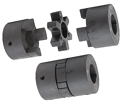
Given these advantages, elastomeric materials are popular choices for various flexible shaft couplings, including jaw couplings, tire couplings, and spider couplings. However, it is essential to select the right elastomer material based on the specific application requirements, such as temperature range, chemical compatibility, and torque capacity.
“`
Temperature and Speed Limits for Different Shaft Coupling Types
The temperature and speed limits of shaft couplings vary depending on the materials and design of the coupling. Manufacturers provide specific guidelines and ratings for each coupling type. Below are general temperature and speed limits for some common shaft coupling types:
1. Elastomeric Couplings:
Elastomeric couplings, such as jaw couplings and tire couplings, typically have temperature limits ranging from -40°C to 100°C (-40°F to 212°F). The speed limits for elastomeric couplings are generally up to 5,000 RPM, but some designs may allow higher speeds.
2. Metallic Couplings:
Metallic couplings, like gear couplings and disc couplings, can handle a wider temperature range, typically from -50°C to 200°C (-58°F to 392°F). The speed limits for metallic couplings vary based on the size and design, but they can range from 3,000 RPM to over 10,000 RPM.
3. Grid Couplings:
Grid couplings have temperature limits similar to metallic couplings, ranging from -50°C to 200°C (-58°F to 392°F). The speed limits for grid couplings are typically in the range of 3,000 to 5,000 RPM.
4. Oldham Couplings:
Oldham couplings usually have temperature limits from -30°C to 100°C (-22°F to 212°F) and speed limits ranging from 1,000 to 5,000 RPM.
5. Beam Couplings:
Beam couplings generally have temperature limits from -40°C to 120°C (-40°F to 248°F) and speed limits between 5,000 to 10,000 RPM.
6. Fluid Couplings:
Fluid couplings are suitable for a wide range of temperatures, often from -50°C to 300°C (-58°F to 572°F). The speed limits depend on the size and design of the fluid coupling but can extend to several thousand RPM.
It’s important to note that these are general guidelines, and the actual temperature and speed limits may vary based on the specific coupling manufacturer, material quality, and application requirements. Always refer to the manufacturer’s documentation and technical specifications for accurate and up-to-date temperature and speed limits for a particular shaft coupling model.
“`
Best Practices for Installing a Shaft Coupling for Optimal Performance
Proper installation of a shaft coupling is crucial for ensuring optimal performance and preventing premature wear or failure. Follow these best practices to install a shaft coupling correctly:
1. Shaft Alignment:
Ensure that both the driving and driven shafts are properly aligned before installing the coupling. Misalignment can lead to increased stress on the coupling and other connected components, reducing efficiency and causing premature wear. Use alignment tools, such as dial indicators or laser alignment systems, to achieve accurate shaft alignment.
2. Cleanliness:
Before installation, clean the shaft ends and the coupling bore thoroughly. Remove any dirt, debris, or residue that could interfere with the coupling’s fit or cause misalignment.
3. Lubrication:
Apply the recommended lubricant to the coupling’s contact surfaces, such as the bore and shaft ends. Proper lubrication ensures smooth installation and reduces friction during operation.
4. Correct Fit:
Ensure that the coupling is the correct size and type for the application. Use couplings with the appropriate torque and speed ratings to match the equipment’s requirements.
5. Fastening:
Use the recommended fastening methods, such as set screws or keyways, to securely attach the coupling to the shafts. Make sure the fasteners are tightened to the manufacturer’s specifications to prevent loosening during operation.
6. Spacer or Adapter:
If required, use a spacer or adapter to properly position the coupling on the shafts and maintain the desired distance between the driving and driven components.
7. Avoid Shaft Damage:
Be careful during installation to avoid damaging the shaft ends, especially when using set screws or other fastening methods. Shaft damage can lead to stress concentrations and eventual failure.
8. Check Runout:
After installation, check the coupling’s runout using a dial indicator to ensure that it rotates smoothly and without wobbling. Excessive runout can indicate misalignment or improper fit.
9. Periodic Inspection:
Regularly inspect the coupling and its components for signs of wear, misalignment, or damage. Perform routine maintenance as recommended by the manufacturer to prevent issues from worsening over time.
10. Follow Manufacturer’s Guidelines:
Always follow the manufacturer’s installation instructions and guidelines. Different types of couplings may have specific installation requirements that need to be adhered to for optimal performance and safety.
By following these best practices, you can ensure that your shaft coupling is installed correctly, maximizing its efficiency and reliability in your mechanical power transmission system.
“`

editor by CX 2024-03-07
China factory FCL Elastic Column Pin Coupling 90 100 180 Shaft Flexible Couplings
Product Description
FCL elastic column pin coupling shaft flexible couplings
Product Description
Flexible Couplings is widely used, owing to its advantages: compact designing, easy installation,convenient maintenance, small size and light weight. As long as the relative displacement between shaftsis kept within the specified tolerance, B couplings will operate the best function and have a longer working life.Thus it is greatly demanded in medium and minor power transmission systems driven by motors,such as speed reducers, hoists, compressors,conveyers, spinning and weaving machines and ball mills.
Mighty can produce full series of FCL Couplings:FCL .
Material: Cast Iron;
ore type: pilot bore, finished bore for set screw, bearing, keyway, taper bush;
Surface finish: phosphate coated.
Our coupling type as below:
Chain Coupling: 3012, 4012, 4014, 4018, 5014, 5016, 5018, 6018, 6571, 6571, 8018, 8571, 8571, 1571, 12018, 12571
Tyre Coupling: A40,A50,A60,A70,A80,A90,A100,A110,A120,A140,A160,A180,A200
HRC Coupling: 70, 90, 110, 130, 150, 180, 230, 280
MH Coupling: 45, 55, 65, 80, 90, 115, 130, 145, 175, 200
NM Coupling: 50, 67, 82, 97, 112, 128, 148, 168, 194, 214, 240, 265
Jaw Coupling: L035, L050, L070, L075, L090, L095, L099, L100, L110, L150, L190, L225
Flange Coupling: 90, 100, 112, 125, 140, 160, 180, 200, 224, 250, 280, 315, 355, 400, 450, 560, 630
Pin Coupling: 67, 83, 102, 134, 178, 204, 254, 318
Spacer Coupling: F40, F50, F60, F70, F80, F90, F100, F110, F120, F140
Jaw Coupling: L035, L050, L070, L075, L090, L095, L099, L100, L110, L150, L190, L22
PACKING
OUR COMPANY
ZheJiang Mighty Machinery Co., Ltd. specializes in offering best service and the most competitive price for our customer.
After over 10 years’ hard work, MIGHTY’s business has grown rapidly and become an important partner for oversea clients in the industrial field and become a holding company for 3 manufacturing factories.
MIGHTY’s products have obtained reputation of domestic and oversea customers with taking advantage of technology, management, quality and very competitive price.
Your satisfaction is the biggest motivation for our work, choose us to get high quality products and best service.
OUR FACTORY
Main Products:
Timing belt pulleys, timing bars, timing belt clamping plates.
Locking elements and shrink discs: could be alternative for Ringfeder, Sati, Chiaravalli, BEA, KBK, Tollok, etc.
V belt pulleys and taper lock bush.
Sprockets, idler, and plate wheels.
Gears and racks: spur gear, helical gear, bevel gear, worm gear, gear rack.
Shaft couplings: miniature coupling, curved tooth coupling, chain coupling, HRC coupling, normex coupling, FCL coupling, GE coupling, rigid and flexible coupling, jaw coupling, disc coupling, multi-beam coupling, universal joint, torque limiter, shaft collars.
Forging, Casting, Stamping Parts.
Other customized power transmission products and Machining Parts (OEM).
Application
1. Engineering: machine tools, foundry equipments, conveyors, compressors, painting systems, etc.
2. Pharmaceuticals& Food Processing: pulp mill blowers, conveyor in warehouse, agitators, grain, boiler, bakery machine, labeling machine, robots, etc.
3. Agriculture Industries: cultivator, rice winnower tractor, harvester, rice planter, farm equipment, etc.
4. Texitile Mills: looms, spinning, wrappers, high-speed auto looms, processing machine, twister, carding machine, ruler calendar machine, high speed winder, etc.
5. Printing Machinery: newspaper press, rotary machine, screen printer machine, linotype machine offset printer, etc.
6. Paper Industries: chipper roll grinder, cut off saw, edgers, flotation cell and chips saws, etc.
7. Building Construction Machinery: buffers, elevator floor polisher mixing machine, vibrator, hoists, crusher, etc.
8. Office Equipments: typewriter, plotters, camera, money drive, money sorting machine, data storage equipment, etc.
9. Glass and Plastic Industries: conveyor, carton sealers, grinders, creeper paper manufacturing machine, lintec backing, etc.
10. Home Appliances: vacuum cleaner, laundry machine, icecream machine, sewing machine, kitchen equipments, etc.
FAQ
Q: Are you trading company or manufacturer ?
A: We are factory.
Q: How long is your delivery time?
A: Generally it is 5-10 days if the goods are in stock. or it is 15-20 days if the goods are not in stock, it is according to quantity.
Q: Do you provide samples ? is it free or extra ?
A: Yes, we could offer the sample for free charge but do not pay the cost of freight.
Q: What is your terms of payment ?
A: Payment=1000USD, 30% T/T in advance ,balance before shippment.
If you have another question, pls feel free to contact us as below:
Contacts
We warmly welcome friends from domestic and abroad come to us for business negotiation and cooperation for mutual benefit. To supply customers excellent quality products with good price and punctual delivery time is our responsibility.
Any question or inquiry, pls contact us without hesitate, we assure any of your inquiry will get our prompt attention and reply!
Specific Safety Precautions When Working with Shaft Couplings
Working with shaft couplings involves handling rotating machinery and mechanical components. To ensure the safety of personnel and prevent accidents, specific safety precautions should be followed during installation, maintenance, and operation:
1. Lockout-Tagout (LOTO):
Prior to any work on machinery involving couplings, implement a lockout-tagout procedure to isolate the equipment from its power source. This ensures that the machinery cannot be accidentally energized during maintenance or repair, protecting workers from potential hazards.
2. Personal Protective Equipment (PPE):
Always wear appropriate personal protective equipment (PPE), including safety goggles, gloves, and appropriate clothing, when working with shaft couplings. PPE helps protect against potential hazards such as flying debris, sharp edges, or contact with moving parts.
3. Proper Training and Supervision:
Only trained and authorized personnel should work with shaft couplings. Ensure that workers have the necessary knowledge and experience to handle the equipment safely. Adequate supervision may be required, especially for less-experienced personnel.
4. Inspection and Maintenance:
Regularly inspect shaft couplings and associated components for signs of wear, damage, or misalignment. Address any issues promptly to prevent equipment failure and potential accidents.
5. Follow Manufacturer’s Guidelines:
Adhere to the manufacturer’s instructions and guidelines for installation, operation, and maintenance of the specific coupling model. Improper use or deviation from recommended procedures may compromise safety and void warranties.
6. Avoid Overloading:
Do not exceed the torque and speed limits specified by the coupling manufacturer. Overloading a coupling can lead to premature failure and pose safety risks to operators and nearby equipment.
7. Shaft Guards and Enclosures:
Install appropriate guards and enclosures to prevent accidental contact with rotating shafts and couplings. These safety measures help reduce the risk of entanglement and injuries.
8. Zero Energy State:
Ensure that all stored energy in the equipment, such as compressed air or hydraulic pressure, is released and the equipment is in a zero energy state before starting work.
9. Avoid Loose Clothing and Jewelry:
Remove or secure loose clothing, jewelry, and other items that could get caught in moving parts.
10. Maintain a Clean Work Area:
Keep the work area clean and free from clutter to avoid tripping hazards and facilitate safe movement around the machinery.
By following these safety precautions, personnel can minimize the risks associated with working with shaft couplings and create a safer working environment for everyone involved.
“`
Comparing Shaft Couplings with Other Types of Couplings in Performance
Shaft couplings are essential components in mechanical power transmission systems, and their performance characteristics vary depending on the coupling type. Let’s compare shaft couplings with other common types of couplings:
1. Shaft Couplings:
Shaft couplings come in various designs, including flexible and rigid couplings. They are widely used in a broad range of applications due to their ability to transmit torque and accommodate misalignments between rotating shafts. Flexible shaft couplings, with elastomeric or metallic elements, offer good misalignment compensation and damping characteristics. Rigid couplings, on the other hand, provide precise torque transmission and are ideal for applications where shafts are well-aligned.
2. Gear Couplings:
Gear couplings are robust and designed for heavy-duty applications. They consist of two external gear hubs with internal gear teeth that mesh together. Gear couplings can handle high torque, high-speed, and angular misalignment. They are often used in demanding industries such as steel, mining, and paper manufacturing.
3. Grid Couplings:
Grid couplings feature a flexible grid element between the two halves of the coupling. They provide excellent shock absorption and misalignment compensation. Grid couplings are commonly used in pumps, compressors, and other industrial machinery.
4. Disc Couplings:
Disc couplings utilize flexible metallic discs to transmit torque and compensate for misalignment. They offer high torsional stiffness, making them suitable for applications requiring precise motion control, such as robotics and CNC machines.
5. Jaw Couplings:
Jaw couplings consist of two hubs with elastomeric spider inserts. They are easy to install, have good misalignment capabilities, and offer electrical isolation between shafts. Jaw couplings are widely used in light to medium-duty applications.
6. Oldham Couplings:
Oldham couplings have three discs—two outer discs with slots and a central disc with a tongue that fits into the slots. They provide excellent angular misalignment compensation while maintaining constant velocity between shafts. Oldham couplings are commonly used in printing machines and conveyors.
7. Beam Couplings:
Beam couplings are made from a single piece of flexible material with spiral cuts. They offer good misalignment compensation and torsional flexibility, making them suitable for precision equipment like encoders and servo motors.
The choice of coupling depends on the specific requirements of the application, including torque, speed, misalignment compensation, environmental conditions, and space limitations. Each coupling type has its strengths and limitations, and selecting the right coupling is crucial to ensure optimal performance and reliability in the mechanical system.
“`
What is a Shaft Coupling and Its Role in Mechanical Power Transmission?
A shaft coupling is a mechanical device used to connect two shafts together at their ends, allowing for the transmission of mechanical power from one shaft to another. It serves as an essential component in various machinery and industrial applications where rotational motion needs to be transmitted between two shafts that are not perfectly aligned or are separated by a distance.
The role of a shaft coupling in mechanical power transmission includes the following:
1. Power Transmission:
The primary function of a shaft coupling is to transmit power from a driving shaft to a driven shaft. When the driving shaft rotates, the coupling transfers the rotational motion to the driven shaft, enabling the driven equipment to perform its intended function.
2. Misalignment Compensation:
In real-world applications, it is often challenging to achieve perfect alignment between two shafts due to manufacturing tolerances or dynamic conditions. Shaft couplings are designed to accommodate different types of misalignment, such as angular, parallel, and axial misalignment, allowing the equipment to function smoothly even when the shafts are not perfectly aligned.
3. Vibration Damping:
Shaft couplings can help dampen vibrations and shocks caused by uneven loads or sudden changes in the operating conditions. This vibration damping feature protects the connected components from damage and contributes to the overall system’s reliability.
4. Overload Protection:
In some cases, a shaft coupling can act as a safety device by providing overload protection. When the connected machinery experiences excessive torque or shock loads, certain types of couplings can disengage or shear to prevent damage to the equipment.
5. Torque and Speed Conversion:
Shaft couplings can be designed to provide torque and speed conversion between the driving and driven shafts. This allows for adaptation to different operating conditions and varying torque requirements in the connected machinery.
6. Flexible Connection:
Shaft couplings with flexible elements, such as elastomeric inserts or flexible discs, provide a flexible connection that can absorb shocks and misalignments. This flexibility helps reduce stress on the connected equipment and extends its lifespan.
Overall, shaft couplings are essential components in mechanical power transmission systems, enabling the efficient transfer of rotational motion between shafts while accommodating misalignments and providing protection against overloads and vibrations. The selection of the appropriate coupling type and design depends on the specific requirements of the application, including the type of misalignment, torque capacity, and operating conditions.
“`

editor by CX 2023-10-20
China 1-1/2 Inch~6 Inch Aluminum Pin Lug Coupling for Hoses a coupling reaction
Item Description
Pin Lug Couplings
Application: For suction and discharge hose coupling.
Substance: The Pin Lug Couplings have aluminum shanks with brass swivel nuts and NPSM thread, NST&lparFire Hose Thread)
Threads: NPSM, NST
Measurement: 1-1&sol2″ to 6″
Seal: NBR, EPDM
Specification of Pin Lug Couplings:
| Pin Lug Couplings | ||
| Portion No. | Thread | Inch Size |
| GNPLM150 | NPSM | 1-1&sol2″ |
| GNPLT150 | NST | 1-1&sol2″ |
| GNPLM200. | NPSM | two” |
| GNPLM250. | NPSM | 2-1&sol2″ |
| GNPLT250 | NST | two-1&sol2″ |
| GNPLM300 | NPSM | three” |
| GNPLM400 | NPSM | four” |
| GNPLM600 | NPSM | six” |
| Standard: | DIN |
|---|---|
| Material: | Aluminium |
| Connection: | Male |
| Surface Treatment: | Without Treatment |
| Head Type: | Round |
| Application: | Hose Coupling |
###
| Samples: |
US$ 5/Piece
1 Piece(Min.Order) |
|---|
###
| Customization: |
|---|
###
| Pin Lug Couplings | ||
| Part No. | Thread | Inch Size |
| GNPLM150 | NPSM | 1-1/2" |
| GNPLT150 | NST | 1-1/2" |
| GNPLM200. | NPSM | 2" |
| GNPLM250. | NPSM | 2-1/2" |
| GNPLT250 | NST | 2-1/2" |
| GNPLM300 | NPSM | 3" |
| GNPLM400 | NPSM | 4" |
| GNPLM600 | NPSM | 6" |
Types of Couplings
A coupling is a device that connects two shafts together. It transmits power from one end to another and is used for joining rotating equipment. A coupling is flexible and can accommodate a certain amount of end movement and misalignment. This allows for more flexibility in applications. Various types of couplings are available, and each one serves a specific purpose.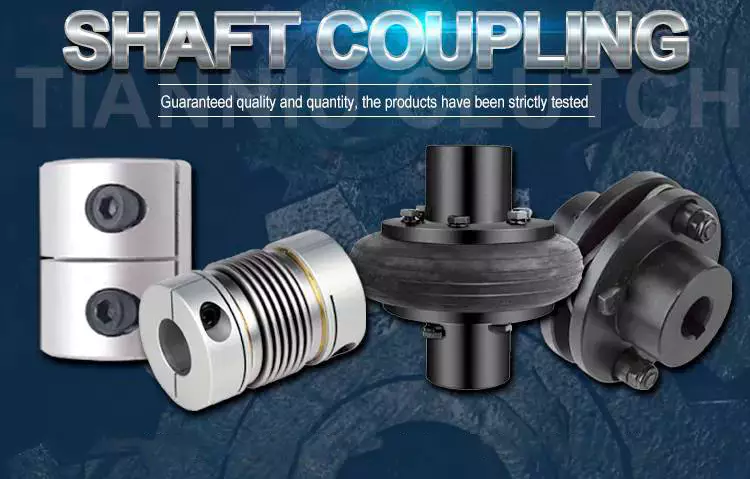
Shaft couplings
There are many types of shaft couplings, and they are used in a wide range of applications. The type you need depends on the torque, speed, and horsepower you need, as well as the size of the shaft and its spatial limitations. You may also need to consider whether the coupling will accommodate misalignment.
Some shaft couplings are flexible, while others are rigid. Flexible couplings can accommodate up to two degrees of misalignment. They are available in different materials, including aluminum, stainless steel, and titanium. They can also be known by different names, depending on the industry. Some couplings can also be used in a single or multiple-shaft application.
The first type of shaft coupling is a rigid coupling, which consists of two parts that fit together tightly around the shafts. These couplings are designed to have more flexibility than sleeved models, and they can be used on fixed shafts as well. The flanged coupling, on the other hand, is designed for heavy loads and is made of two perpendicular flanges. The flanges are large enough to accommodate screws and are generally used with heavy-duty applications.
CZPT shaft couplings are a great choice if you’re looking for a shaft coupling that delivers high performance, durability, and low cost. These metal disc-style couplings provide low backlash and high torsional stiffness. Their high misalignment tolerance reduces reaction loads on connected components, which makes them ideal for high-speed precision applications. Available in single and double-disc models, they have torque ratings of up to 2,200 in-lbs. (250N) and are available in fourteen sizes.
When using shaft couplings, it is important to choose the right type for your application. Backlash can cause a shaft coupling to break or become unusable. In order to prevent this from happening, you should replace worn or loose parts, and ensure that the hub and key are evenly positioned with the shaft. If you’re using a shaft coupling in a motion-control system, it is important to keep the torque level consistent.
Flexible couplings
Flexible couplings are a type of coupling used to connect two shafts. They are made of rubber or plastic and allow for axial movement of the connected equipment. They do not require lubrication and are resistant to fatigue failure. Flexible couplings are useful for a number of applications. A common type of flexible coupling is the gear coupling, which has gear teeth inside its sleeve. Another type of flexible coupling is the metallic membrane coupling. A metallic membrane coupling is flexible due to flexing metallic discs.
One major disadvantage of flexible couplings is their inability to fit certain types of pipe. This is because most couplings need to be stretched to fit the pipe. This problem is often the result of a change in pipe technology. Traditionally, drain and soil pipe is made of ductile iron or cast iron. Today, most pipes are made of PVC, which has a larger outside diameter than either cast or ductile iron. Because of these changes in pipe technology, many coupling manufacturers have not updated their mold sizing.
Flexible couplings can be either metallic, elastomeric, or a combination of the three. While there are some common characteristics of each type, you should always consider the tradeoffs of each type before choosing one. Generally, the most important considerations when selecting a flexible coupling are torque, misalignment, and ease of assembly and maintenance.
Flexible couplings are used in a wide range of industries. They are useful for connecting two pipes to ensure torque transfer. Although the types available are different, these are the most adaptable couplings in the market. They can withstand movement, vibration, and bending without causing any damage to the piping.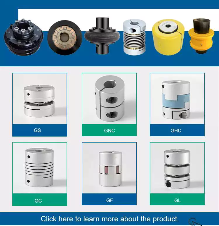
Clutch couplings
A clutch coupling connects two rotating shafts by friction. The clutch engages power when the engine is running, disengaging power when the brake is applied. Clutch couplings are used in applications where the speed of a machine is variable or where continuous service is required. The clutch can transmit power, torque, and axial force.
Clutch couplings come in a variety of styles and configurations. Some couplings are flexible, while others are rigid. Flexible couplings are available in a variety of materials, including stainless steel and aluminum. Some couplings also have a non-backlash design, which helps compensate for misalignment.
Clutch couplings may be synchronous or asynchronous. Synchronous couplings engage and disengage automatically when the driven machine exceeds its output speed. These couplings are synchronized by a synchronizing mechanism. When the output speed is exceeded, the synchronizing mechanism initiates the engagement process. The synchronizing mechanism does not engage or disengage when the output speed drops.
High speed clutches are available from a variety of manufacturers. Some manufacturers offer OEM assembly, repair services, and third-party logistics. These manufacturers serve the automotive, chemical, food, and wood industries, as well as the oilfield and material handling industries. Custom clutches can be manufactured for specific applications and can be fitted with additional features, such as precision machined teeth or keyway slots and grooves.
Couplings are available in PCE, C/T, and metric bores. Typically, the size of the input and output shafts will determine which type of coupling is needed. In addition, clutches may be configured for intermediate or high speeds, depending on the required torque.
Clamped couplings
Clamped couplings are commonly used in a variety of industries. They can be used in medical equipment, dental equipment, military equipment, laboratory equipment, and in precision industrial controls. They are available in a wide variety of sizes and keyways. This type of coupling offers a number of advantages, including ease of installation and quick and easy replacement.
A clamp coupling connects two parts by compressing them together. The clamping elements can be formed in a variety of ways, but they all have a gap between their surfaces. This friction squeezes the two parts together, much like pulling two rubber gloves apart. This type of coupling is also useful for joining two hoses or piping units.
Clamped couplings are designed with a single or double clamping shaft. The clamping parts are mounted in two halves and are held together by eight socket head cap screws. They offer high torque capacity and require little installation space. Their high rigidity ensures good positioning accuracy, making them ideal for dynamic drives. In addition, they are wear-free and offer simple radial assembly.
The invention relates to a method and system for clamping pipes to a tank vessel. This invention also relates to a method of loading and unloading tank vessels. The method can be used in oil production platforms and other platforms. A single point mooring method is also used in oil production platforms.
Clamped couplings can also be flexible. They can join two shafts together while allowing a small amount of end movement and misalignment. These couplings may also be used in the assembly of motors and gearboxes.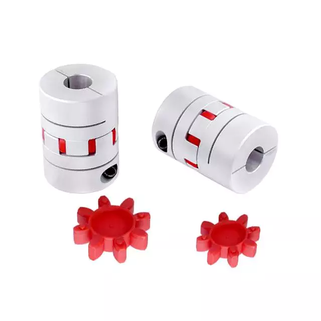
CZPT’s coupling
CZPT couplings are designed to be flexible, allowing them to accommodate misaligned shafts and transmit torque in either direction. They are made with three discs, two hubs, and a center that are arranged with grooves and fins. These features allow for two degrees of freedom during assembly, and can accommodate misalignment of up to 5% of the shaft diameter.
CZPT couplings have many uses. For example, they can be used to join two parallel coaxial rotating shafts. Their ability to transmit torque at the same rotation mechanism and speed makes them ideal for applications where electrical currents may be a problem. Because the couplings are not made of metal, they are electrically isolated. Designers should test their couplings during the prototype stage to ensure they are working properly.
The CZPT coupling consists of two hubs with one slot on each. An intermediate disk is located between the two hubs. The discs are used to reduce or prevent wear on other machine parts. CZPT couplings are inexpensive and easy to replace. They also have electrical insulation, which makes them easy to repair or replace.
CZPT couplings are a popular choice for stepper motor-driven positioning stages. The plastic center disc offers electrical isolation and absorbs shocks from frequent start/stops. These couplings are available in through-hub and blind-bore styles and can be installed in many applications.
CZPT couplings also allow for small degrees of shaft misalignment. This allows them to function in systems where shaft access is limited. They are easily removed without tools.

editor by CX 2023-03-28
China Good Service Low Price Camlock Coupling Pin Lug Pellet Pistol Ldhc Couplings coupling definition
Product Description
Solution Description
ZYfire Hose Company, established in 2000, we analysis and generate Lay flat frac hose, hearth hose, rack hose, industrial hose, forestry hose, snow-making hose, irrigation hose, drag hose, potable h2o hose, No-dig pipe rehabilitation liner, TPR layflat hose, hose couplings, landing valves and other fire combating equipments.
Content: Light alloy
Also obtainable in anodized or tough coated version and with extra locking gadget
These hose couplings are ideal for hoses with wall thickness of 2, 8 – 3, 2 mm. The binding is composed of 3 segments with screws and nuts.
Positive aspects:
one. Assembly with easy resources (hexagon crucial)
2. Coupling and binding re-usable
three. Binding guards the endangered selection amongst tail end and hose
four. Limited duration supports problem-totally free rolling up
five. Substantial pressures are attainable due to the fact of massive firmness of the binding
6. No mounted hook when pulling the hose because of the bevel at the binding
Major Products
Business Profile
FAQ
|
/ Piece | |
1,000 Pieces (Min. Order) |
###
| Certification: | CE |
|---|---|
| Surface Treatment: | Epoxy Painting |
| Material: | Carbon Steel |
| Application: | Hose |
| Transport Package: | Cartons |
| Specification: | Coupling |
###
| Samples: |
US$ 5/Piece
1 Piece(Min.Order) |
|---|
###
| Customization: |
|---|
Types of Coupling
A coupling is a device used to join two shafts together and transmit power. Its primary function is to join rotating equipment and allows for some end movement and misalignment. This article discusses different types of coupling, including Magnetic coupling and Shaft coupling. This article also includes information on Overload safety mechanical coupling.
Flexible beam coupling
Flexible beam couplings are universal joints that can deal with shafts that are offset or at an angle. They consist of a tube with couplings at both ends and a thin, flexible helix in the middle. This makes them suitable for use in a variety of applications, from motion control in robotics to attaching encoders to shafts.
These couplings are made of one-piece materials and are often made of stainless steel or aluminium alloy. However, they can also be made of acetal or titanium. While titanium and acetal are less common materials, they are still suitable for high-torque applications. For more information about beam couplings, contact CZPT Components.
Flexible beam couplings come in a variety of types and sizes. W series couplings are good for general purpose applications and are relatively economical. Stainless steel versions have increased torque capacity and torsional stiffness. Flexible beam couplings made of aluminum are ideal for servo and reverse motion. They are also available with metric dimensions.
Flexible beam couplings are made of aluminum alloy or stainless steel. Their patented slot pattern provides low bearing load and high torsional rigidity. They have a long operational life. They also require zero maintenance and can handle angular offset. Their advantages outweigh the disadvantages of traditional beam couplings.
Magnetic coupling
Magnetic coupling transfers torque from one shaft to another using a magnetic field. These couplings can be used on various types of machinery. These types of transmissions are very useful in many situations, especially when you need to move large amounts of weight. The magnetic field is also very effective at reducing friction between the two shafts, which can be extremely helpful if you’re moving heavy items or machinery.
Different magnetic couplings can transmit forces either linearly or rotated. Different magnetic couplings have different topologies and can be made to transmit force in various geometric configurations. Some of these types of couplings are based on different types of materials. For example, a ceramic magnetic material can be used for applications requiring high temperature resistance.
Hybrid couplings are also available. They have a hybrid design, which allows them to operate in either an asynchronous or synchronous mode. Hysterloy is an alloy that is easily magnetized and is used in synchronous couplings. A synchronous magnetic coupling produces a coupled magnetic circuit.
Magnetic coupling is a key factor in many physical processes. In a crystal, molecules exhibit different magnetic properties, depending on their atomic configuration. Consequently, different configurations produce different amounts of magnetic coupling. The type of magnetic coupling a molecule exhibits depends on the exchange parameter Kij. This exchange parameter is calculated by using quantum chemical methods.
Magnetic couplings are most commonly used in fluid transfer pump applications, where the drive shaft is hermetically separated from the fluid. Magnetic couplings also help prevent the transmission of vibration and axial or radial loads through the drive shaft. Moreover, they don’t require external power sources, since they use permanent magnets.
Shaft coupling
A shaft coupling is a mechanical device that connects two shafts. The coupling is designed to transmit full power from one shaft to the other, while keeping the shafts in perfect alignment. It should also reduce transmission of shock loads. Ideally, the coupling should be easy to connect and maintain alignment. It should also be free of projecting parts.
The shaft couplings that are used in machines are typically made of two types: universal coupling and CZPT coupling. CZPT couplings are designed to correct for lateral misalignment and are composed of two flanges with tongues and slots. They are usually fitted with pins. The T1 tongue is fitted into flange A, while the T2 tongue fits into flange B.
Another type of shaft coupling is known as a “sliced” coupling. This type of coupling compensates for inevitable shaft misalignments and provides high torque. Machined slits in the coupling’s outer shell help it achieve high torsional stiffness and excellent flexibility. The design allows for varying engagement angles, making it ideal for many different applications.
A shaft coupling is an important component of any machine. Proper alignment of the two shafts is vital to avoid machine breakdowns. If the shafts are misaligned, extra force can be placed on other parts of the machine, causing vibration, noise, and damage to the components. A good coupling should be easy to connect and should ensure precise alignment of the shaft. Ideally, it should also have no projecting parts.
Shaft couplings are designed to tolerate a certain amount of backlash, but it must be within a system’s threshold. Any angular movement of the shaft beyond this angle is considered excessive backlash. Excessive backlash results in excessive wear, stress, and breakage, and may also cause inaccurate alignment readings. It is therefore imperative to reduce backlash before the shaft alignment process.
Overload safety mechanical coupling
Overload safety mechanical couplings are devices that automatically disengage when the torque applied to them exceeds a specified limit. They are an efficient way to protect machinery and reduce the downtime associated with repairing damaged machinery. The advantage of overload couplings is their fast reaction time and ease of installation.
Overload safety mechanical couplings can be used in a wide range of applications. Their automatic coupling mechanisms can be used on any face or edge. In addition, they can be genderless, incorporating both male and female coupling features into a single mechanism. This means that they are both safe and gender-neutral.
Overload safety couplings protect rotating power transmission components from overloads. Overload protection devices are installed on electric motors to cut off power if the current exceeds a certain limit. Likewise, fluid couplings in conveyors are equipped with melting plug elements that allow the fluid to escape when the system becomes too hot. Mechanical force transmission devices, such as shear bolts, are designed with overload protection in mind.
A common design of an overload safety mechanical coupling consists of two or more arms and hubs separated by a plastic spider. Each coupling body has a set torque threshold. Exceeding this threshold may damage the spider or damage the jaws. In addition, the spider tends to dampen vibration and absorb axial extension. This coupling style is nearly backlash free, electrically isolating, and can tolerate very little parallel misalignment.
A mechanical coupling may also be a universal joint or jaw-clutch coupling. Its basic function is to connect the driver and driven shafts, and limits torque transfer. These devices are typically used in heavy-duty industries, such as steel plants and rolling mills. They also work well with industrial conveyor systems.
CZPT Pulley
The CZPT Pulley coupling family offers a comprehensive range of couplings for motors of all types. Not only does this range include standard motor couplings, but also servo couplings, which require ultra-precise control. CZPT Pulley couplings are also suitable for engine applications where high shocks and vibrations are encountered.
CZPT Pulley couplings have a “sliced” body structure, which allows for excellent torsional stiffness and strength. They are corrosion-resistant and can withstand high rotational speeds. The couplings’ design also ensures accurate shaft rotation while limiting shaft misalignment.
CZPT Pulley has introduced the CPU Pin Type couplings, which are effective at damping vibration and maintain zero backlash. They are also made from aluminum and are capable of absorbing heat. They come with recessed tightening screws. They can handle speeds up to 4,000 RPM, and are RoHS-compliant.

editor by CX 2023-03-27