Product Description
Product Description
1. The allowable compensation quantity listed in the table refers to the relative offset of 2 axes formed by the comprehensive factors such as vibration, shock, deformation and temperature change caused by manufacturing error, installation error and working load change under working condition.
2. The maximum allowable angular deviation of the coupling shall not exceed ±5°.
The maximum opening value is a circular hole or a tapered hole with a keyway.
Main applications:
DWZ disc eddy current brake is mainly used as load in loading dynamometer equipment. it is experimental apparatus which can measure the dynamic mechanical properties, especially in dynamic loading test whose power value is small or tiny, also can be treated as suction power devices of other dynamic devices.
DW series disc eddy current dynamometer is, is that add device for measuring torque and rotational speed on DWZ series disc eddy current brake, it is experimental apparatus which can measure the dynamic mechnical properties, especial in dynamic loading test whose power value is small or tiny.
CW eddy current brake as a load is mainly used to measure the mechanical characteristics of inspection equipment, it and other control instrument (including loading apparatus, torque speed sensor and torque power acquisition instrument etc.) can be composed of eddy current dynamometer can be used for performance testing of the internal combustion engine, motor, gas turbine, automobile and its dynamic mechanical components, compared with other power measuring device, the CW series power measuring device has the advantages of reliability, high stability and practicability.
| Eddy current brake/dynamometer | Rated Power | Rated torque | Rated speed | Maximum rotational speed | Turning inertia | Maximum excitation voltage | Maximum excitation Current | Cooling water pressure | Flow of the cooling water |
| DWZ/DW-0.75 | 0.75 | 5 | 2000-2600 | 16000 | 0.002 | 80 | 3 | 0.1~0.3 | 1 |
| DWZ/DW-3 | 3 | 10 | 2000-2600 | 14000 | 0.003 | 80 | 3 | 0.1~0.3 | 2 |
| DWZ/DW-6 | 6 | 25 | 2000-2600 | 14000 | 0.003 | 80 | 3 | 0.1~0.3 | 3 |
| DWZ/DW-10 | 10 | 50 | 2000-2600 | 13000 | 0.01 | 80 | 3 | 0.1~0.3 | 4.5 |
| DWZ/DW-16 | 16 | 70 | 2000-2600 | 13000 | 0.02 | 80 | 3.5 | 0.1~0.3 | 6.5 |
| DWZ/DW-25 | 25 | 120 | 2000-2600 | 11000 | 0.05 | 80 | 3.5 | 0.1~0.3 | 15 |
| DWZ/DW-40 | 40 | 160 | 2000-2600 | 10000 | 0.1 | 90 | 4 | 0.1~0.3 | 25 |
| DWZ/DW-63 | 63 | 250 | 2000-2600 | 9000 | 0.18 | 90 | 4 | 0.1~0.3 | 45 |
| DWZ/DW-100 | 100 | 400 | 2000-2600 | 8500 | 0.32 | 120 | 4 | 0.1~0.3 | 60 |
| DWZ/DW-160 | 160 | 600 | 2000-2600 | 8000 | 0.52 | 120 | 5 | 0.1~0.3 | 100 |
| DWZ/DW-250 | 250 | 1100 | 2000-2600 | 7000 | 1.8 | 150 | 5 | 0.2~0.4 | 180 |
| DWZ/DW-300 | 300 | 1600 | 2000-2600 | 6000 | 2.7 | 150 | 5 | 0.2~0.4 | 210 |
| DWZ/DW-400 | 400 | 2200 | 2000-2600 | 5000 | 3.6 | 180 | 10 | 0.2~0.4 | 300 |
| DWZ/DW-630 | 630 | 3600 | 2000-2600 | 5000 | 5.3 | 180 | 10 | 0.2~0.4 | 450 |
/* January 22, 2571 19:08:37 */!function(){function s(e,r){var a,o={};try{e&&e.split(“,”).forEach(function(e,t){e&&(a=e.match(/(.*?):(.*)$/))&&1

Specific Safety Precautions When Working with Shaft Couplings
Working with shaft couplings involves handling rotating machinery and mechanical components. To ensure the safety of personnel and prevent accidents, specific safety precautions should be followed during installation, maintenance, and operation:
1. Lockout-Tagout (LOTO):
Prior to any work on machinery involving couplings, implement a lockout-tagout procedure to isolate the equipment from its power source. This ensures that the machinery cannot be accidentally energized during maintenance or repair, protecting workers from potential hazards.
2. Personal Protective Equipment (PPE):
Always wear appropriate personal protective equipment (PPE), including safety goggles, gloves, and appropriate clothing, when working with shaft couplings. PPE helps protect against potential hazards such as flying debris, sharp edges, or contact with moving parts.
3. Proper Training and Supervision:
Only trained and authorized personnel should work with shaft couplings. Ensure that workers have the necessary knowledge and experience to handle the equipment safely. Adequate supervision may be required, especially for less-experienced personnel.
4. Inspection and Maintenance:
Regularly inspect shaft couplings and associated components for signs of wear, damage, or misalignment. Address any issues promptly to prevent equipment failure and potential accidents.
5. Follow Manufacturer’s Guidelines:
Adhere to the manufacturer’s instructions and guidelines for installation, operation, and maintenance of the specific coupling model. Improper use or deviation from recommended procedures may compromise safety and void warranties.
6. Avoid Overloading:
Do not exceed the torque and speed limits specified by the coupling manufacturer. Overloading a coupling can lead to premature failure and pose safety risks to operators and nearby equipment.
7. Shaft Guards and Enclosures:
Install appropriate guards and enclosures to prevent accidental contact with rotating shafts and couplings. These safety measures help reduce the risk of entanglement and injuries.
8. Zero Energy State:
Ensure that all stored energy in the equipment, such as compressed air or hydraulic pressure, is released and the equipment is in a zero energy state before starting work.
9. Avoid Loose Clothing and Jewelry:
Remove or secure loose clothing, jewelry, and other items that could get caught in moving parts.
10. Maintain a Clean Work Area:
Keep the work area clean and free from clutter to avoid tripping hazards and facilitate safe movement around the machinery.
By following these safety precautions, personnel can minimize the risks associated with working with shaft couplings and create a safer working environment for everyone involved.
“`
Temperature and Speed Limits for Different Shaft Coupling Types
The temperature and speed limits of shaft couplings vary depending on the materials and design of the coupling. Manufacturers provide specific guidelines and ratings for each coupling type. Below are general temperature and speed limits for some common shaft coupling types:
1. Elastomeric Couplings:
Elastomeric couplings, such as jaw couplings and tire couplings, typically have temperature limits ranging from -40°C to 100°C (-40°F to 212°F). The speed limits for elastomeric couplings are generally up to 5,000 RPM, but some designs may allow higher speeds.
2. Metallic Couplings:
Metallic couplings, like gear couplings and disc couplings, can handle a wider temperature range, typically from -50°C to 200°C (-58°F to 392°F). The speed limits for metallic couplings vary based on the size and design, but they can range from 3,000 RPM to over 10,000 RPM.
3. Grid Couplings:
Grid couplings have temperature limits similar to metallic couplings, ranging from -50°C to 200°C (-58°F to 392°F). The speed limits for grid couplings are typically in the range of 3,000 to 5,000 RPM.
4. Oldham Couplings:
Oldham couplings usually have temperature limits from -30°C to 100°C (-22°F to 212°F) and speed limits ranging from 1,000 to 5,000 RPM.
5. Beam Couplings:
Beam couplings generally have temperature limits from -40°C to 120°C (-40°F to 248°F) and speed limits between 5,000 to 10,000 RPM.
6. Fluid Couplings:
Fluid couplings are suitable for a wide range of temperatures, often from -50°C to 300°C (-58°F to 572°F). The speed limits depend on the size and design of the fluid coupling but can extend to several thousand RPM.
It’s important to note that these are general guidelines, and the actual temperature and speed limits may vary based on the specific coupling manufacturer, material quality, and application requirements. Always refer to the manufacturer’s documentation and technical specifications for accurate and up-to-date temperature and speed limits for a particular shaft coupling model.
“`
Best Practices for Installing a Shaft Coupling for Optimal Performance
Proper installation of a shaft coupling is crucial for ensuring optimal performance and preventing premature wear or failure. Follow these best practices to install a shaft coupling correctly:
1. Shaft Alignment:
Ensure that both the driving and driven shafts are properly aligned before installing the coupling. Misalignment can lead to increased stress on the coupling and other connected components, reducing efficiency and causing premature wear. Use alignment tools, such as dial indicators or laser alignment systems, to achieve accurate shaft alignment.
2. Cleanliness:
Before installation, clean the shaft ends and the coupling bore thoroughly. Remove any dirt, debris, or residue that could interfere with the coupling’s fit or cause misalignment.
3. Lubrication:
Apply the recommended lubricant to the coupling’s contact surfaces, such as the bore and shaft ends. Proper lubrication ensures smooth installation and reduces friction during operation.
4. Correct Fit:
Ensure that the coupling is the correct size and type for the application. Use couplings with the appropriate torque and speed ratings to match the equipment’s requirements.
5. Fastening:
Use the recommended fastening methods, such as set screws or keyways, to securely attach the coupling to the shafts. Make sure the fasteners are tightened to the manufacturer’s specifications to prevent loosening during operation.
6. Spacer or Adapter:
If required, use a spacer or adapter to properly position the coupling on the shafts and maintain the desired distance between the driving and driven components.
7. Avoid Shaft Damage:
Be careful during installation to avoid damaging the shaft ends, especially when using set screws or other fastening methods. Shaft damage can lead to stress concentrations and eventual failure.
8. Check Runout:
After installation, check the coupling’s runout using a dial indicator to ensure that it rotates smoothly and without wobbling. Excessive runout can indicate misalignment or improper fit.
9. Periodic Inspection:
Regularly inspect the coupling and its components for signs of wear, misalignment, or damage. Perform routine maintenance as recommended by the manufacturer to prevent issues from worsening over time.
10. Follow Manufacturer’s Guidelines:
Always follow the manufacturer’s installation instructions and guidelines. Different types of couplings may have specific installation requirements that need to be adhered to for optimal performance and safety.
By following these best practices, you can ensure that your shaft coupling is installed correctly, maximizing its efficiency and reliability in your mechanical power transmission system.
“`

editor by CX 2024-04-17
China Coupling Manufacturer standard flex flange type universal coupling 45# steel Double universal joint cardan shaft connector coupling and types of coupling
Guarantee: 1 year
Applicable Industries: Garment Retailers, Developing Content Outlets, Producing Plant, Equipment Repair Retailers, Foods & Beverage Manufacturing facility, SWC390WD limited without having flex universal coupling Manufacturing unit direct sale Double universal joint cardan shaft coupling Substantial High quality Farms, Strength & Mining, Other
Custom-made assistance: OEM
Composition: Universal
Versatile or Rigid: Flexible
Normal or Nonstandard: Nonstandard
Substance: Steel
Solution title: Standard flex flange sort universal coupling
Variety: SWC490BF
Software: Power Transmission
Entire body Material: forty five# Steel
Measurement: Regular Measurement
Coloration: Customrized
Surface area Remedy: Paint
MOQ: 1 Set
Certification: ISO9001:2015
Provider: 12 Months
Packaging Specifics: normal export packing and wooden pallets packing
Port: ZheJiang port, China
Scorching Sale
| one. Merchandise Identify | Regular flex flange kind common coupling |
| 2. Sort | SWC490BF |
| three. Application | Shaft Link |
| four. Brand | HangZhou CZPT |
| 5. MOQ | 1 Set |
| 6. Price | EXW price |
| seven. Transport Way | By sea, DHL, Large Quality part axletree brief with out flex sort universal joint coupling Manufacturing facility Price tag industrial tools cardan shaft UPS, Fedex or as customers’ demands |
| 8. Payment Phrases | By means of T/T |
| nine. Shipping and delivery Time | Within fifteen-twenty workdays after deposit or as customers’ need |
| 10. Packaging | 1. Export Picket Box two. Carton Box 3. We can perform according to customers’ demands |
Certifications
Organization Info
Packaging & Grid Coupling casing axial mount grid coupling adaptable shaft connector snake spring forty five# metal Coupling Producer Transport
Apps
FAQ

Functions and Modifications of Couplings
A coupling is a mechanical device that connects two shafts and transmits power. Its main purpose is to join two rotating pieces of equipment together, and it can also be used to allow some end movement or misalignment. There are many different types of couplings, each serving a specific purpose.
Functions
Functions of coupling are useful tools to study the dynamical interaction of systems. These functions have a wide range of applications, ranging from electrochemical processes to climate processes. The research being conducted on these functions is highly interdisciplinary, and experts from different fields are contributing to this issue. As such, this issue will be of interest to scientists and engineers in many fields, including electrical engineering, physics, and mathematics.
To ensure the proper coupling of data, coupling software must perform many essential functions. These include time interpolation and timing, and data exchange between the appropriate nodes. It should also guarantee that the time step of each model is divisible by the data exchange interval. This will ensure that the data exchange occurs at the proper times.
In addition to transferring power, couplings are also used in machinery. In general, couplings are used to join two rotating pieces. However, they can also have other functions, including compensating for misalignment, dampening axial motion, and absorbing shock. These functions determine the coupling type required.
The coupling strength can also be varied. For example, the strength of the coupling can change from negative to positive. This can affect the mode splitting width. Additionally, coupling strength is affected by fabrication imperfections. The strength of coupling can be controlled with laser non-thermal oxidation and water micro-infiltration, but these methods have limitations and are not reversible. Thus, the precise control of coupling strength remains a major challenge.
Applications
Couplings transmit power from a driver to the driven piece of equipment. The driver can be an electric motor, steam turbine, gearbox, fan, or pump. A coupling is often the weak link in a pump assembly, but replacing it is less expensive than replacing a sheared shaft.
Coupling functions have wide applications, including biomedical and electrical engineering. In this book, we review some of the most important developments and applications of coupling functions in these fields. We also discuss the future of the field and the implications of these discoveries. This is a comprehensive review of recent advances in coupling functions, and will help guide future research.
Adaptable couplings are another type of coupling. They are made up of a male and female spline in a polymeric material. They can be mounted using traditional keys, keyways, or taper bushings. For applications that require reversal, however, keyless couplings are preferable. Consider your process speed, maximum load capacity, and torque when choosing an adaptable coupling.
Coupling reactions are also used to make pharmaceutical products. These chemical reactions usually involve the joining of two chemical species. In most cases, a metal catalyst is used. The Ullmann reaction, for instance, is an important example of a hetero-coupling reaction. This reaction involves an organic halide with an organometallic compound. The result is a compound with the general formula R-M-R. Another important coupling reaction involves the Suzuki coupling, which unites two chemical species.
In engineering, couplings are mechanical devices that connect two shafts. Couplings are important because they enable the power to be transmitted from one end to the other without allowing a shaft to separate during operation. They also reduce maintenance time. Proper selection, installation, and maintenance, will reduce the amount of time needed to repair a coupling.
Maintenance
Maintenance of couplings is an important part of the lifecycle of your equipment. It’s important to ensure proper alignment and lubrication to keep them running smoothly. Inspecting your equipment for signs of wear can help you identify problems before they cause downtime. For instance, improper alignment can lead to uneven wear of the coupling’s hubs and grids. It can also cause the coupling to bind when you rotate the shaft manually. Proper maintenance will extend the life of your coupling.
Couplings should be inspected frequently and thoroughly. Inspections should go beyond alignment checks to identify problems and recommend appropriate repairs or replacements. Proper lubrication is important to protect the coupling from damage and can be easily identified using thermography or vibration analysis. In addition to lubrication, a coupling that lacks lubrication may require gaskets or sealing rings.
Proper maintenance of couplings will extend the life of the coupling by minimizing the likelihood of breakdowns. Proper maintenance will help you save money and time on repairs. A well-maintained coupling can be a valuable asset for your equipment and can increase productivity. By following the recommendations provided by your manufacturer, you can make sure your equipment is operating at peak performance.
Proper alignment and maintenance are critical for flexible couplings. Proper coupling alignment will maximize the life of your equipment. If you have a poorly aligned coupling, it may cause other components to fail. In some cases, this could result in costly downtime and increased costs for the company.
Proper maintenance of couplings should be done regularly to minimize costs and prevent downtime. Performing periodic inspections and lubrication will help you keep your equipment in top working order. In addition to the alignment and lubrication, you should also inspect the inside components for wear and alignment issues. If your coupling’s lubrication is not sufficient, it may lead to hardening and cracking. In addition, it’s possible to develop leaks that could cause damage.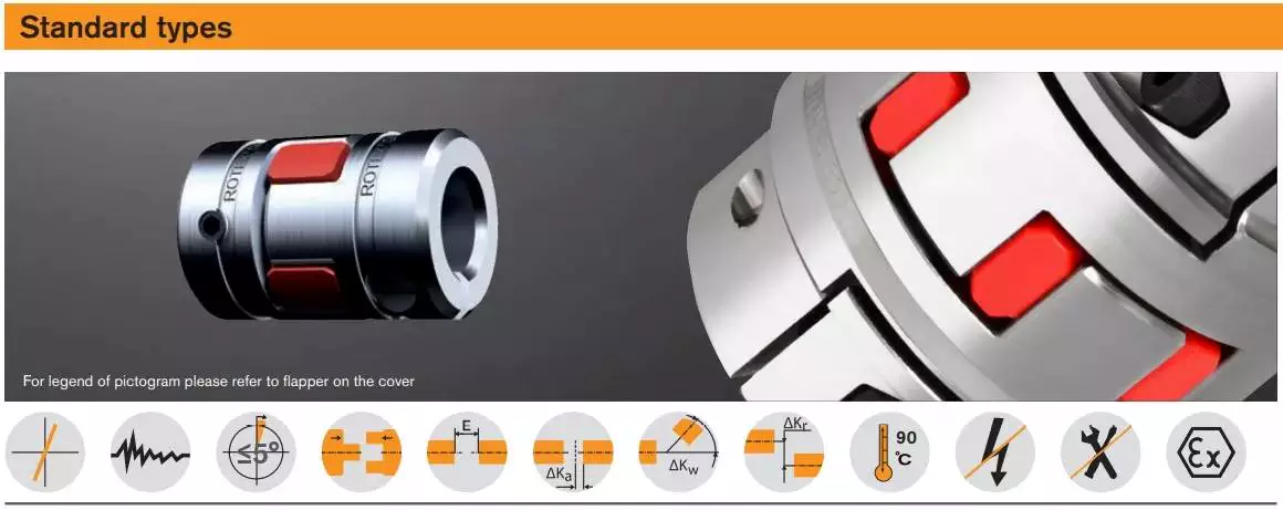
Modifications
The aim of this paper is to investigate the effects of coupling modifications. It shows that such modifications can adversely affect the performance of the coupling mechanism. Moreover, the modifications can be predicted using chemical physics methods. The results presented here are not exhaustive and further research is needed to understand the effects of such coupling modifications.
The modifications to coupling involve nonlinear structural modifications. Four examples of such modifications are presented. Each is illustrated with example applications. Then, the results are verified through experimental and simulated case studies. The proposed methods are applicable to large and complex structures. They are applicable to a variety of engineering systems, including nonlinear systems.
editor by CX 2023-04-17
in Bouake Côte d’Ivoire sales price shop near me near me shop factory supplier Scrap Television Cover TV Cover Fridge Cover Refrigerator Cover Computer Cover Double Shaft Shredding Machine manufacturer best Cost Custom Cheap wholesaler

Hangzhou EPG Co.,Ltd. , was founded in November, 1997. With its 5 wholly owned subsidiaries. We have exported our merchandise to Korea, Turkey, Bulgaria, Romania, Russia, Italy, Norway, the Usa, Canada, and so forth. The new goods incorporate a series of large-tech and large quality chains and sprockets and gears, these kinds of as chains and gearboxes for agricultural machineries, metallurgical chains, escalator action-chains, substantial-speed tooth chains, timing chains, self-lubrication chains, amongst which have type large speed tooth chain for automobile department dynamic box and aerial chains fill in the blanks of chain in China. Scrap tv protect/ Tv set include/ fridge go over/ fridge protect/ computer protect double shaft shredding EPTT
Brief Introduction to Shredder:
The shredEPTTis a widely used EPTT for tearing massive content to small parts, which make them easy for next stage to transportation or recycling. It is composed of one shaft shredder, double shaft shredder, 4 shaft shredder, horizontal big pipe shredder, more compact pipe crusher #8230.
Plastic ShredEPTTEPTT is an excellent EPTT for plastic, paper, wooden, fiber, rubber, natural squander a broad variety of non metallic materials. The measurement of the EPTT necessary for every single project depends on the first size of the material, potential and the ultimate particle dimension preferred.
The shredEPTTseries assortment is controlled by microcomputer, that includes start off, end, reverse features. It is fitted with an automatic overload return system to prevent harm to rotor and other parts. It operates at large torque, lower velocity, with low noise output, suitable for recycling a extensive selection of components.
1. One Shaft Shredder
Software:
The single shaft shredEPTTis mostly utilised for massive block objects, such as die head content, thick wall pipes, and also can be used for film roller, paper and fibers, and so on #8230.
Main people:
one. The blades and blades rack of one shaft shredEPTTcan be demounted on the rotating shaft. It is straightforward to very clear, change and routine maintenance.
2. The rotating blades of one shaft shredEPTTare fixed on the shaft by V condition. It is great for shredding the materials evenly which can make the power consumption is lower and sounds is quite tiny.
3. Every rotating blade of solitary shaft shredEPTThas four reducing edges, right after 1 chopping edge is worn out, it can be altered to other ones. And also with same style to the mounted blade, which has two chopping edges, also when 1 chopping edge is worn out, it can be modify to the other 1.
four. The shaft of one shaft shredEPTTis EPTn by motor via the EPT box, it operates steady, low noise, substantial torque.
5. The substance is pushed by EPT pusher of one shaft shredEPTTautomatically. It functions robust and secure.
six. The electric powered method of solitary shaft shredEPTTis managed by PLC, which make the shaft can rotate in optimistic route, reversal course and end, then to defend the EPTTs working properly.
Product:
| Model | Principal EPTT | Pushing EPTT | Qty rotating blades | Qty mounted blades |
Shaft rotating diameter | Potential (kg) |
Measurement (mm) |
Weight (kg) |
| TSS600 | 22kw | one.5kw | 28 | two | phi252mm | two hundred~400 | 1800x1200x1800 | 2000 |
| TSS800 | 37kw | two.2kw | 38 | two | phi400mm | 500~800 | 2700x1700x2000 | 3200 |
| TSS1000 | 45kw | two.2kw | forty eight | three | phi400mm | seven hundred~one thousand | 2800x2000x2300 | 4300 |
| TSS1200 | 55kw | 3.7kw | 78 | three | phi430mm | a thousand~1500 | 2950x2200x2500 | 5500 |
| TSS1500 | 90kw | three.7kw | 102 | 4 | phi480mm | 1300~1800 | 3100x2550x2700 | 7800 |
| TSS2000 | 55kw*2 | 5.5kw | 177 | 4 | phi480mm | 1800~2500 | 3300x3050x2800 | 9500 |
two. EPTT Shaft Shredder
Application:
The double shaft shredEPTTis mainly utilised for tough materials, such as barrel, basket, panel content, wooden, vehicle tires and even big bale film etc #8230..
Major characters:
1. The shredding cabinet of double shaft shredEPTTis manufactured of EPTT thickness metal panel with precision machining. It is mounted by massive angle hexagonal bolts and with powerful inlet hopper. All these is to guarantee the big and hefty content can be put straight into the shredding cupboards
2. The rotating blades of double shaft shredEPTTare with EPTT developed to the thickness, shape and arranging series which make certain it is sturdy reducing potential, sharpening cutting edge and then make it working higher successfully.
three. Lower velocity operating, low sound and significantly less powEPTTflying of double shaft shredder.
4. The blades of double shaft shredEPTTare made of EPTT alloy metal, sturdy and EPTT time working.
5. The electrical technique of double shaft shredEPTTis controlled by PLC, which make the shaft can rotate in good route, reversal course and cease, then to safeguard the EPTTs operating safely.
Design:
| Product | EPT EPTT(KW) | Qty of blades | Dimension of shredding chamber | Potential (kg/h) |
| TDS600 | 15 | twelve | 600*550 mm | three hundred~800 |
| TDS800 | 37 | 16 | 800*600 mm | 500~1500 |
| TDS1000 | thirty times2 | 20 | 1000*700 mm | 1000~2000 |
| TDS1200 | 37 times2 | 24 | 1200*800 mm | 1500~2500 |
| TDS1500 | 45kw times2 | 22 | 1600*900 mm | 2000~3000 |
3. EPTT single-shaft shredder/plastic film shredder
Software:
EPT for PE PP movie, EPT film, PE PP bags, film roller, bundle film, wrap movie, LD EPTT movie, BOPP movie…
Primary figures:
one. EPT designed double shaft shredEPTTfor gentle content.
two. The blades and blades rack can be demounted on the rotating shaft. It is simple to obvious, modify and upkeep.
three. The rotating blades of movie shredEPTTare fastened on the shaft by V shape. It is good for shredding the materials evenly which can make the energy use is minimal and sound is quite small.
4. Every rotating blade of one shaft shredEPTThas four cutting edges, following one particular cutting edge is worn out, it can be changed to other ones. And also with very same layout to the fastened blade, which has two slicing edges, also when one particular chopping edge is worn out, it can be change to the other one particular.
five. The shaft of film shredEPTTis EPTn by motor through the EPT box, it operates stable, low sound, large torque.
6. The electric technique of film shredEPTTis managed by PLC, which make the shaft can rotate in optimistic course, reversal path and end, then to defend the EPTTs operating safely.
Product:
| Model | EPT EPTT(KW) | Qty of blades | Diameter of shaft | Capacity (kg/h) |
| TFS600 | eighteen.5 times2 | fifty four | oslash255 mm | 500~650 |
| TFS800 | 22 times2 | 82 | oslash255 mm | 750~900 |
| TFS1000 | 30 times2 | a hundred | oslash300 mm | 900~1100 |
| TFS1200 | 37 times2 | 122 | oslash300 mm | 1200~1500 |
| TFS1500 | 45kw times2 | 158 | oslash320 mm | 1600~2000 |
4. Four Shaft Shredder
Software:
1. Bucket items: PE bucket, steel drum, paint bucket, intermediate -bulk container (IBC) and dustbin
two. Wastes: EPTT waste, medical waste, kitchen area squander, EPTT waste, park waste
3. Plastic goods: PE bottle, PE body, PE block, PE can
four. EPT goods: EPT profile, oil filter, car shell, pop-best can, metal can
5. Paper: newspaper, card paper, corrugated paper, duplicate paper
6. EPT EPTs: refrigerator, circuit board, notebook shell, Television set shell, CD disk
7. Glass
Primary characters:
4 shaft shredEPTTis weighty-obligation EPTT. They have rewards in stXiHu (West EPT) Dis.Hu (West EPT) Dis.rdization and modularization style, large interchangeability for their elements. Their blades are made of EPTT alloy metal with large energy, strong anti-put on and reparability. The EPT element requires gain of four motors, large earth EPT containers to make primary shafts rotate at diverse speeds. The electrical component requires edge of PLC program and contact EPT management with video monitor system and the automated detecting overload safety function. They have lower rotation speed, massive torque and low sound people. So they have gained customers’ EPTT and received popularity in the shredding method in the recycle sector They fit for shredding massive and difficult objects such as vehicle physique, solid EPTT waste ,health care waste, e-waste, PE pail, PE body, PE bottle, steel can, metal pail, intertexture bag, fridge, electric circuit board, paper box, wood and so on.
5. Bundle ShredEPTTCrusher EPTT
6. EPT Shredder/Granulator
OrEPTTflowing approach:
Buyer specifications #8594Scheme designed #8594confirmed by buyers #8594orEPTTfixed #8594manufacturing #8594trial operating in our manufacturing unit #8594confirmed by buyers #8594shipped #8594engineer obtainable overEPTT #8594EPTT existence soon after sales companies
Contacts:
REEPTH EPTTry is an knowledgeable and expert manufacturing for series plastic washing recycling EPTT/ plastic granulating recycling EPTT incXiHu (West EPT) Dis.Hu (West EPT) Dis. ET bottle recycling EPTTs, PE PP film recycling EPTTs, plastic PE PP PS Ab muscles PET Laptop PVC LD EPTT LLD BOPP granulating line, h2o remedy for the waste h2o from washing line, and auXiHu (West EPT) Dis.liary tools for plastic recycling….
If you are intriguing more details of our items, please make contact with with us no hesitation!
Mob: -152-50376571

