Product Description
Product Description
| OEM | 2611125718 26111227420 | Parts Name | Drive shaft Coupling | |||||||
| Diameter | 96mm | Trademark | YTK or Customized | |||||||
| Raw Material | Rubber & Steel | Transport Packing | Neutral Packing & Customized | |||||||
| Exportation | ZheJiang Port | Bearing Quality | ZV3 Level | |||||||
| Warranty | One Year | Product Customized | Available | |||||||
| HS Code |
8708999990 |
Delivery Time | 7-30 days | |||||||
| Origin | XingTai China | Minimum | 2 | Φ30 | CB | Φ35 Φ40 | 3535730 | Φ60 | ||
| Φ60 | Φ60 | 6 | Φ65 |
/* January 22, 2571 19:08:37 */!function(){function s(e,r){var a,o={};try{e&&e.split(“,”).forEach(function(e,t){e&&(a=e.match(/(.*?):(.*)$/))&&1
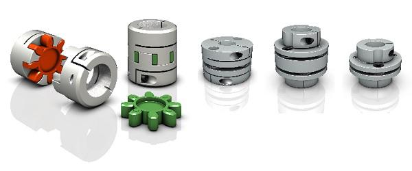
How to Select the Right Shaft Coupling for Specific Torque and Speed Requirements
Selecting the appropriate shaft coupling involves considering the specific torque and speed requirements of the application. Here’s a step-by-step guide to help you choose the right coupling:
1. Determine Torque and Speed:
Identify the torque and speed requirements of the application. Torque is the rotational force required to transmit power between the shafts, usually measured in Nm (Newton-meters) or lb-ft (pound-feet). Speed refers to the rotational speed of the shafts, typically measured in RPM (revolutions per minute).
2. Calculate Torque Capacity:
Check the torque capacity of various shaft couplings. Manufacturers provide torque ratings for each coupling type and size. Ensure that the selected coupling has a torque capacity that exceeds the application’s torque requirements.
3. Consider Misalignment:
If the application involves significant shaft misalignment due to thermal expansion, vibration, or other factors, consider flexible couplings with good misalignment compensation capabilities. Elastomeric or beam couplings are popular choices for such applications.
4. Assess Operating Speed:
For high-speed applications, choose couplings with high rotational speed ratings to avoid resonance issues and potential coupling failure. High-speed couplings may have specialized designs, such as disk or diaphragm couplings.
5. Evaluate Environmental Conditions:
If the coupling will operate in harsh environments with exposure to chemicals, moisture, or extreme temperatures, select couplings made from corrosion-resistant materials or with protective coatings.
6. Check Torsional Stiffness:
In applications requiring precision motion control, consider couplings with high torsional stiffness to minimize torsional backlash and maintain accurate positioning. Bellows or Oldham couplings are examples of couplings with low torsional backlash.
7. Size and Space Constraints:
Ensure that the selected coupling fits within the available space and aligns with the shaft dimensions. Be mindful of any installation limitations, especially in confined spaces or applications with limited radial clearance.
8. Consult Manufacturer’s Data:
Refer to the manufacturer’s catalogs and technical data sheets for detailed information on each coupling’s torque and speed ratings, misalignment capabilities, materials, and other relevant specifications.
9. Consider Cost and Maintenance:
Compare the costs and maintenance requirements of different couplings. While some couplings may have higher upfront costs, they could offer longer service life and reduced maintenance costs in the long run.
By following these steps and considering the specific torque and speed requirements of your application, you can select the right shaft coupling that will ensure efficient power transmission and reliable performance for your mechanical system.
“`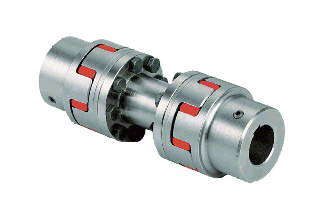
Do Shaft Couplings Require Regular Maintenance, and if so, What Does it Involve?
Yes, shaft couplings do require regular maintenance to ensure their optimal performance, extend their service life, and prevent unexpected failures. The maintenance frequency may vary based on factors such as the coupling type, application, operating conditions, and the manufacturer’s recommendations. Here’s what regular maintenance for shaft couplings typically involves:
1. Visual Inspection:
Regularly inspect the coupling for signs of wear, damage, or misalignment. Check for cracks, corrosion, and worn-out elastomeric elements (if applicable). Look for any abnormal movement or rubbing between the coupling components during operation.
2. Lubrication:
If the shaft coupling requires lubrication, follow the manufacturer’s guidelines for the appropriate lubricant type and frequency. Lubrication helps reduce friction, wear, and noise in the coupling.
3. Alignment Check:
Monitor shaft alignment periodically. Misalignment can lead to premature coupling failure and damage to connected equipment. Make adjustments as needed to keep the shafts properly aligned.
4. Torque Check:
For bolted couplings, periodically check the torque on the bolts to ensure they remain securely fastened. Loose bolts can lead to misalignment and reduce coupling performance.
5. Replace Worn Components:
If any coupling components show signs of wear or damage beyond acceptable limits, replace them promptly with genuine replacement parts from the manufacturer.
6. Environmental Considerations:
In harsh environments with exposure to chemicals, moisture, or extreme temperatures, take additional measures to protect the coupling, such as applying corrosion-resistant coatings or using special materials.
7. Monitoring Coupling Performance:
Implement a monitoring system to track coupling performance and detect any changes or abnormalities early on. This could include temperature monitoring, vibration analysis, or other condition monitoring techniques.
8. Professional Inspection:
Periodically have the coupling and connected machinery inspected by qualified professionals to identify any potential issues that may not be apparent during regular inspections.
By adhering to a regular maintenance schedule and taking proactive measures to address potential issues, you can ensure that your shaft couplings operate reliably and efficiently throughout their service life, minimizing downtime and improving overall system performance.
“`
Can a Damaged Shaft Coupling Lead to Equipment Failure and Downtime?
Yes, a damaged shaft coupling can lead to equipment failure and downtime in mechanical power transmission systems. Shaft couplings play a critical role in connecting rotating shafts and transmitting power between them. When a coupling becomes damaged or fails to function properly, several negative consequences can arise:
1. Misalignment Issues:
A damaged coupling may no longer be able to compensate for misalignments between the connected shafts. Misalignment can cause excessive vibration, increased wear, and premature failure of bearings and other connected components. Over time, these issues can lead to equipment breakdown and unplanned downtime.
2. Vibration and Shock Loads:
Without the damping properties of a functional coupling, vibrations and shock loads from the driven equipment can transmit directly to the driving shaft and other parts of the system. Excessive vibrations can lead to fatigue failure, cracking, and damage to the equipment, resulting in reduced operational efficiency and increased downtime.
3. Overloading and Torque Transmission:
A damaged coupling may not effectively transmit the required torque between the driving and driven shafts. In applications where the coupling is a safety device (e.g., shear pin couplings), failure to disengage during overloading situations can lead to equipment overload and damage.
4. Increased Wear and Tear:
A damaged coupling can lead to increased wear on other parts of the system. Components such as bearings, seals, and gears may experience higher stress and wear, reducing their lifespan and increasing the likelihood of breakdowns.
5. Reduced System Reliability:
A functional shaft coupling contributes to the overall reliability of the mechanical system. A damaged coupling compromises this reliability, making the system more prone to failures and unplanned maintenance.
6. Downtime and Production Loss:
When a shaft coupling fails, it often results in unscheduled downtime for repairs or replacement. Downtime can be costly for industries that rely on continuous production processes and can lead to production losses and missed delivery deadlines.
7. Safety Hazards:
In certain applications, such as heavy machinery or industrial equipment, a damaged coupling can create safety hazards for workers and surrounding equipment. Sudden failures or uncontrolled movements may pose risks to personnel and property.
Regular inspection, maintenance, and prompt replacement of damaged shaft couplings are essential to prevent equipment failure, minimize downtime, and ensure safe and efficient operation of mechanical systems. It is crucial to address any signs of coupling wear or damage immediately to avoid potential catastrophic failures and costly disruptions to operations.
“`

editor by CX 2024-04-30
China wholesaler Diameter 26mm Length 35mm Disc Coupling Aluminum Alloy Double Diaphragm Clamp Series Shaft Couplings 6*8mm
Product Description
Product Description
1. The allowable compensation quantity listed in the table refers to the relative offset of 2 axes formed by the comprehensive factors such as vibration, shock, deformation and temperature change caused by manufacturing error, installation error and working load change under working condition.
2. The maximum allowable angular deviation of the coupling shall not exceed ±5°.
The maximum opening value is a circular hole or a tapered hole with a keyway.
Main applications:
DWZ disc eddy current brake is mainly used as load in loading dynamometer equipment. it is experimental apparatus which can measure the dynamic mechanical properties, especially in dynamic loading test whose power value is small or tiny, also can be treated as suction power devices of other dynamic devices.
DW series disc eddy current dynamometer is, is that add device for measuring torque and rotational speed on DWZ series disc eddy current brake, it is experimental apparatus which can measure the dynamic mechnical properties, especial in dynamic loading test whose power value is small or tiny.
CW eddy current brake as a load is mainly used to measure the mechanical characteristics of inspection equipment, it and other control instrument (including loading apparatus, torque speed sensor and torque power acquisition instrument etc.) can be composed of eddy current dynamometer can be used for performance testing of the internal combustion engine, motor, gas turbine, automobile and its dynamic mechanical components, compared with other power measuring device, the CW series power measuring device has the advantages of reliability, high stability and practicability.
| Eddy current brake/dynamometer | Rated Power | Rated torque | Rated speed | Maximum rotational speed | Turning inertia | Maximum excitation voltage | Maximum excitation Current | Cooling water pressure | Flow of the cooling water |
| DWZ/DW-0.75 | 0.75 | 5 | 2000-2600 | 16000 | 0.002 | 80 | 3 | 0.1~0.3 | 1 |
| DWZ/DW-3 | 3 | 10 | 2000-2600 | 14000 | 0.003 | 80 | 3 | 0.1~0.3 | 2 |
| DWZ/DW-6 | 6 | 25 | 2000-2600 | 14000 | 0.003 | 80 | 3 | 0.1~0.3 | 3 |
| DWZ/DW-10 | 10 | 50 | 2000-2600 | 13000 | 0.01 | 80 | 3 | 0.1~0.3 | 4.5 |
| DWZ/DW-16 | 16 | 70 | 2000-2600 | 13000 | 0.02 | 80 | 3.5 | 0.1~0.3 | 6.5 |
| DWZ/DW-25 | 25 | 120 | 2000-2600 | 11000 | 0.05 | 80 | 3.5 | 0.1~0.3 | 15 |
| DWZ/DW-40 | 40 | 160 | 2000-2600 | 10000 | 0.1 | 90 | 4 | 0.1~0.3 | 25 |
| DWZ/DW-63 | 63 | 250 | 2000-2600 | 9000 | 0.18 | 90 | 4 | 0.1~0.3 | 45 |
| DWZ/DW-100 | 100 | 400 | 2000-2600 | 8500 | 0.32 | 120 | 4 | 0.1~0.3 | 60 |
| DWZ/DW-160 | 160 | 600 | 2000-2600 | 8000 | 0.52 | 120 | 5 | 0.1~0.3 | 100 |
| DWZ/DW-250 | 250 | 1100 | 2000-2600 | 7000 | 1.8 | 150 | 5 | 0.2~0.4 | 180 |
| DWZ/DW-300 | 300 | 1600 | 2000-2600 | 6000 | 2.7 | 150 | 5 | 0.2~0.4 | 210 |
| DWZ/DW-400 | 400 | 2200 | 2000-2600 | 5000 | 3.6 | 180 | 10 | 0.2~0.4 | 300 |
| DWZ/DW-630 | 630 | 3600 | 2000-2600 | 5000 | 5.3 | 180 | 10 | 0.2~0.4 | 450 |
/* January 22, 2571 19:08:37 */!function(){function s(e,r){var a,o={};try{e&&e.split(“,”).forEach(function(e,t){e&&(a=e.match(/(.*?):(.*)$/))&&1
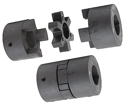
Specific Safety Precautions When Working with Shaft Couplings
Working with shaft couplings involves handling rotating machinery and mechanical components. To ensure the safety of personnel and prevent accidents, specific safety precautions should be followed during installation, maintenance, and operation:
1. Lockout-Tagout (LOTO):
Prior to any work on machinery involving couplings, implement a lockout-tagout procedure to isolate the equipment from its power source. This ensures that the machinery cannot be accidentally energized during maintenance or repair, protecting workers from potential hazards.
2. Personal Protective Equipment (PPE):
Always wear appropriate personal protective equipment (PPE), including safety goggles, gloves, and appropriate clothing, when working with shaft couplings. PPE helps protect against potential hazards such as flying debris, sharp edges, or contact with moving parts.
3. Proper Training and Supervision:
Only trained and authorized personnel should work with shaft couplings. Ensure that workers have the necessary knowledge and experience to handle the equipment safely. Adequate supervision may be required, especially for less-experienced personnel.
4. Inspection and Maintenance:
Regularly inspect shaft couplings and associated components for signs of wear, damage, or misalignment. Address any issues promptly to prevent equipment failure and potential accidents.
5. Follow Manufacturer’s Guidelines:
Adhere to the manufacturer’s instructions and guidelines for installation, operation, and maintenance of the specific coupling model. Improper use or deviation from recommended procedures may compromise safety and void warranties.
6. Avoid Overloading:
Do not exceed the torque and speed limits specified by the coupling manufacturer. Overloading a coupling can lead to premature failure and pose safety risks to operators and nearby equipment.
7. Shaft Guards and Enclosures:
Install appropriate guards and enclosures to prevent accidental contact with rotating shafts and couplings. These safety measures help reduce the risk of entanglement and injuries.
8. Zero Energy State:
Ensure that all stored energy in the equipment, such as compressed air or hydraulic pressure, is released and the equipment is in a zero energy state before starting work.
9. Avoid Loose Clothing and Jewelry:
Remove or secure loose clothing, jewelry, and other items that could get caught in moving parts.
10. Maintain a Clean Work Area:
Keep the work area clean and free from clutter to avoid tripping hazards and facilitate safe movement around the machinery.
By following these safety precautions, personnel can minimize the risks associated with working with shaft couplings and create a safer working environment for everyone involved.
“`
Temperature and Speed Limits for Different Shaft Coupling Types
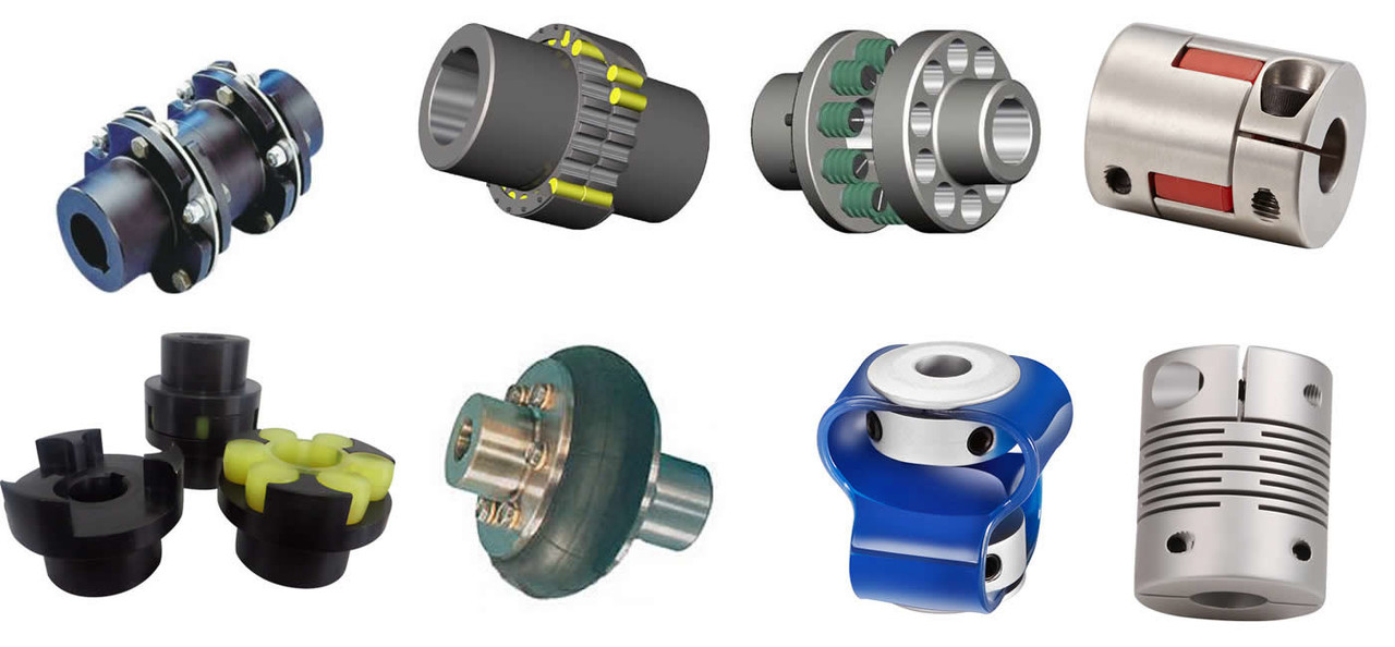
The temperature and speed limits of shaft couplings vary depending on the materials and design of the coupling. Manufacturers provide specific guidelines and ratings for each coupling type. Below are general temperature and speed limits for some common shaft coupling types:
1. Elastomeric Couplings:
Elastomeric couplings, such as jaw couplings and tire couplings, typically have temperature limits ranging from -40°C to 100°C (-40°F to 212°F). The speed limits for elastomeric couplings are generally up to 5,000 RPM, but some designs may allow higher speeds.
2. Metallic Couplings:
Metallic couplings, like gear couplings and disc couplings, can handle a wider temperature range, typically from -50°C to 200°C (-58°F to 392°F). The speed limits for metallic couplings vary based on the size and design, but they can range from 3,000 RPM to over 10,000 RPM.
3. Grid Couplings:
Grid couplings have temperature limits similar to metallic couplings, ranging from -50°C to 200°C (-58°F to 392°F). The speed limits for grid couplings are typically in the range of 3,000 to 5,000 RPM.
4. Oldham Couplings:
Oldham couplings usually have temperature limits from -30°C to 100°C (-22°F to 212°F) and speed limits ranging from 1,000 to 5,000 RPM.
5. Beam Couplings:
Beam couplings generally have temperature limits from -40°C to 120°C (-40°F to 248°F) and speed limits between 5,000 to 10,000 RPM.
6. Fluid Couplings:
Fluid couplings are suitable for a wide range of temperatures, often from -50°C to 300°C (-58°F to 572°F). The speed limits depend on the size and design of the fluid coupling but can extend to several thousand RPM.
It’s important to note that these are general guidelines, and the actual temperature and speed limits may vary based on the specific coupling manufacturer, material quality, and application requirements. Always refer to the manufacturer’s documentation and technical specifications for accurate and up-to-date temperature and speed limits for a particular shaft coupling model.
“`
Best Practices for Installing a Shaft Coupling for Optimal Performance
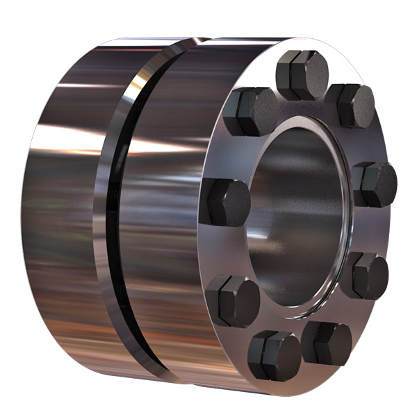
Proper installation of a shaft coupling is crucial for ensuring optimal performance and preventing premature wear or failure. Follow these best practices to install a shaft coupling correctly:
1. Shaft Alignment:
Ensure that both the driving and driven shafts are properly aligned before installing the coupling. Misalignment can lead to increased stress on the coupling and other connected components, reducing efficiency and causing premature wear. Use alignment tools, such as dial indicators or laser alignment systems, to achieve accurate shaft alignment.
2. Cleanliness:
Before installation, clean the shaft ends and the coupling bore thoroughly. Remove any dirt, debris, or residue that could interfere with the coupling’s fit or cause misalignment.
3. Lubrication:
Apply the recommended lubricant to the coupling’s contact surfaces, such as the bore and shaft ends. Proper lubrication ensures smooth installation and reduces friction during operation.
4. Correct Fit:
Ensure that the coupling is the correct size and type for the application. Use couplings with the appropriate torque and speed ratings to match the equipment’s requirements.
5. Fastening:
Use the recommended fastening methods, such as set screws or keyways, to securely attach the coupling to the shafts. Make sure the fasteners are tightened to the manufacturer’s specifications to prevent loosening during operation.
6. Spacer or Adapter:
If required, use a spacer or adapter to properly position the coupling on the shafts and maintain the desired distance between the driving and driven components.
7. Avoid Shaft Damage:
Be careful during installation to avoid damaging the shaft ends, especially when using set screws or other fastening methods. Shaft damage can lead to stress concentrations and eventual failure.
8. Check Runout:
After installation, check the coupling’s runout using a dial indicator to ensure that it rotates smoothly and without wobbling. Excessive runout can indicate misalignment or improper fit.
9. Periodic Inspection:
Regularly inspect the coupling and its components for signs of wear, misalignment, or damage. Perform routine maintenance as recommended by the manufacturer to prevent issues from worsening over time.
10. Follow Manufacturer’s Guidelines:
Always follow the manufacturer’s installation instructions and guidelines. Different types of couplings may have specific installation requirements that need to be adhered to for optimal performance and safety.
By following these best practices, you can ensure that your shaft coupling is installed correctly, maximizing its efficiency and reliability in your mechanical power transmission system.
“`

editor by CX 2024-04-17
China Best Sales Universal Joints Shaft Coupling Motor Disc Coupler Machine Shaft Coupler Steering Connector
Product Description
Specification OF Universal Joint —Speedway:
Product Description
Drive Shaft Description:
| Item | Universal Joints Shaft Coupling Motor Disc Coupler Machine Shaft Coupler Steering Connector |
| OEM | Universal Joints Shaft Coupling |
| Material | 20Cr or 20CrMnTi |
| Use | After market |
| MOQ | 50 cps |
We provide propeller shaft OEM service and we can also produce propeller shaft according to your samples and drawings.
Package and Delivery:
Neutral Packing Or Customerized Packing.
We accept customerized brand packing if the quantity is good.
Neutral Packing means each propeller shaft is packed with foam polybags, then it will be put into box, and all propeller shafts are packed in cartons finally.
All of the products are well packed.
Delivery time is 35-45 days as normal.
Packing show
Company Profile
Certifications
FAQ
/* January 22, 2571 19:08:37 */!function(){function s(e,r){var a,o={};try{e&&e.split(“,”).forEach(function(e,t){e&&(a=e.match(/(.*?):(.*)$/))&&1

Specific Safety Precautions When Working with Shaft Couplings
Working with shaft couplings involves handling rotating machinery and mechanical components. To ensure the safety of personnel and prevent accidents, specific safety precautions should be followed during installation, maintenance, and operation:
1. Lockout-Tagout (LOTO):
Prior to any work on machinery involving couplings, implement a lockout-tagout procedure to isolate the equipment from its power source. This ensures that the machinery cannot be accidentally energized during maintenance or repair, protecting workers from potential hazards.
2. Personal Protective Equipment (PPE):
Always wear appropriate personal protective equipment (PPE), including safety goggles, gloves, and appropriate clothing, when working with shaft couplings. PPE helps protect against potential hazards such as flying debris, sharp edges, or contact with moving parts.
3. Proper Training and Supervision:
Only trained and authorized personnel should work with shaft couplings. Ensure that workers have the necessary knowledge and experience to handle the equipment safely. Adequate supervision may be required, especially for less-experienced personnel.
4. Inspection and Maintenance:
Regularly inspect shaft couplings and associated components for signs of wear, damage, or misalignment. Address any issues promptly to prevent equipment failure and potential accidents.
5. Follow Manufacturer’s Guidelines:
Adhere to the manufacturer’s instructions and guidelines for installation, operation, and maintenance of the specific coupling model. Improper use or deviation from recommended procedures may compromise safety and void warranties.
6. Avoid Overloading:
Do not exceed the torque and speed limits specified by the coupling manufacturer. Overloading a coupling can lead to premature failure and pose safety risks to operators and nearby equipment.
7. Shaft Guards and Enclosures:
Install appropriate guards and enclosures to prevent accidental contact with rotating shafts and couplings. These safety measures help reduce the risk of entanglement and injuries.
8. Zero Energy State:
Ensure that all stored energy in the equipment, such as compressed air or hydraulic pressure, is released and the equipment is in a zero energy state before starting work.
9. Avoid Loose Clothing and Jewelry:
Remove or secure loose clothing, jewelry, and other items that could get caught in moving parts.
10. Maintain a Clean Work Area:
Keep the work area clean and free from clutter to avoid tripping hazards and facilitate safe movement around the machinery.
By following these safety precautions, personnel can minimize the risks associated with working with shaft couplings and create a safer working environment for everyone involved.
“`
Explaining the Concept of Backlash and How It Affects Shaft Coupling Performance
Backlash is the angular movement or play between the mating components of a mechanical system when the direction of motion is reversed. In the context of shaft couplings, backlash refers to the free rotational movement between the connected shafts before the coupling transmits torque from one shaft to the other.
Backlash occurs in certain coupling designs that have features allowing relative movement between the coupling’s mating parts. Common coupling types that may exhibit some degree of backlash include elastomeric couplings (such as jaw couplings), gear couplings, and Oldham couplings.
How Backlash Affects Shaft Coupling Performance:
1. Loss of Precision: In applications requiring precise motion control, backlash can lead to inaccuracies and reduced positional accuracy. For example, in CNC machines or robotics, any rotational play due to backlash can result in positioning errors and decreased machining or movement precision.
2. Reversal Impact: When a reversing load is applied to a coupling, the presence of backlash can lead to a brief period of rotational play before the coupling re-engages, causing a momentary jolt or impact. This impact can lead to increased stress on the coupling and connected components, potentially reducing their lifespan.
3. Dynamic Response: Backlash can affect the dynamic response of the mechanical system. In systems requiring rapid acceleration or deceleration, the initial play due to backlash may create a delay in torque transmission, affecting the system’s responsiveness.
4. Noise and Vibration: Backlash can cause noise and vibration in the system, leading to increased wear and potential fatigue failure of components.
5. Misalignment Compensation: In some flexible coupling designs, a certain amount of backlash is intentionally incorporated to allow for misalignment compensation. While this is a beneficial feature, excessive backlash can compromise the coupling’s performance.
Minimizing Backlash:
Manufacturers often design couplings with specific features to minimize backlash. For instance, some gear couplings employ crowned gear teeth to reduce clearance, while elastomeric couplings may have preloaded elastomeric elements. Precision couplings like zero-backlash or torsionally rigid couplings are engineered to eliminate or minimize backlash for applications requiring high accuracy and responsiveness.
When selecting a coupling, it’s essential to consider the application’s specific requirements regarding precision, speed, reversing loads, and misalignment compensation, as these factors will determine the acceptable level of backlash for optimal performance.
“`
Types of Shaft Couplings and Their Applications in Various Industries
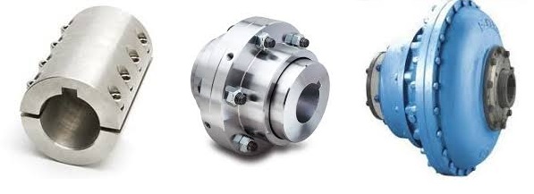
Shaft couplings come in various types, each designed to meet specific application requirements and address different types of misalignment. Here are some common types of shaft couplings and their applications in various industries:
1. Jaw Couplings:
Applications: Jaw couplings are widely used in power transmission applications, including conveyor systems, pumps, compressors, and industrial machinery. They are suitable for moderate torque requirements and provide good misalignment compensation.
2. Gear Couplings:
Applications: Gear couplings are used in heavy-duty industrial applications such as steel mills, paper mills, and mining equipment. They offer high torque capacity and can handle significant misalignments.
3. Disc Couplings:
Applications: Disc couplings are commonly used in precision machinery and automation systems, such as printing presses, machine tools, and robotics. They provide excellent torsional stiffness and are ideal for applications requiring precise positioning.
4. Grid Couplings:
Applications: Grid couplings are used in various industrial applications, including fans, pumps, and compressors. They offer high torque capacity and good shock absorption.
5. Oldham Couplings:
Applications: Oldham couplings are used in applications requiring high misalignment compensation, such as stepper motor drives and motion control systems.
6. Diaphragm Couplings:
Applications: Diaphragm couplings are used in critical applications that demand high torque transmission accuracy, such as aerospace, medical equipment, and semiconductor manufacturing.
7. Elastomeric Couplings:
Applications: Elastomeric couplings, like spider couplings, find applications in general industrial machinery, HVAC systems, and conveyor systems. They provide damping properties and flexibility to accommodate misalignments.
8. Torsionally Rigid Couplings:
Applications: Torsionally rigid couplings are used in applications requiring precise torque transmission, such as precision machining equipment and high-speed spindles.
9. Fluid Couplings:
Applications: Fluid couplings are used in heavy machinery and drivetrains, such as mining equipment, crushers, and marine propulsion systems. They provide smooth acceleration and dampening of shock loads.
10. Magnetic Couplings:
Applications: Magnetic couplings are used in applications where hermetic sealing is required, such as chemical processing, pumps, and mixers. They allow for torque transmission without direct physical contact.
The selection of the appropriate shaft coupling type depends on factors such as torque requirements, speed, misalignment, operating conditions, and the specific needs of the application. Using the right coupling ensures efficient power transmission, protects equipment from misalignment-related issues, and enhances the overall reliability and performance of industrial machinery and systems.
“`

editor by CX 2024-04-08
China best CZPT Customized Motor Single Disc Flexible Shaft Coupling
Product Description
Densen customized Motor Single Disc Flexible Shaft Coupling
| Product Name | Motor Single Disc Flexible Shaft Coupling |
| DN mm | 12~160mm |
| Rated Torque | 25~25000 N·m |
| Allowable speed | 15300~1500 N·m |
| Material | 35CrMo/ZG270/45# steel/Aluminum alloy |
| Application | Widely used in metallurgy, mining, engineering and other fields. |
Product show
Company Information
Equipment
Typical case of diaphragm coupling applied to variable frequency speed control equipment
JMB type coupling is applied to HangZhou Oilfield Thermal Power Plant
According to the requirements of HangZhou Electric Power Corporation, HangZhou Oilfield Thermal Power Plant should dynamically adjust the power generation according to the load of the power grid and market demand, and carry out the transformation of the frequency converter and the suction fan. The motor was originally a 1600KW, 730RPM non-frequency variable speed motor matched by HangZhou Motor Factory. The speed control mode after changing the frequency is manual control. Press the button speed to increase 10RPM or drop 10RPM. The coupling is still the original elastic decoupling coupling, and the elastic de-coupling coupling after frequency conversion is frequently damaged, which directly affects the normal power generation.
It is found through analysis that in the process of frequency conversion speed regulation, the pin of the coupling can not bear the inertia of the speed regulation process (the diameter of the fan impeller is 3.3 meters) and is cut off, which has great damage to the motor and the fan.
Later, they switched to the JMB460 double-diaphragm wheel-type coupling of our factory (patent number: ZL.99246247.9). After 1 hour of destructive experiment and more than 1 year of operation test, the equipment is running very well, and there is no Replace the diaphragm. 12 units have been rebuilt and the operation is in good condition.
Other Application Case
Spare parts
Packaging & Shipping
Contact us

Exploring the Use of Elastomeric Materials in Flexible Shaft Couplings
Elastomeric materials play a crucial role in the design and function of flexible shaft couplings. These materials, commonly known as elastomers, are rubber-like substances that exhibit high elasticity and flexibility. They are widely used in various types of flexible couplings due to their unique properties and benefits:
1. Damping and Vibration Absorption:
Elastomeric materials have excellent damping characteristics, meaning they can absorb and dissipate vibrations and shocks. This property is particularly useful in applications where vibration control is essential to protect sensitive equipment and improve overall system performance.
2. Misalignment Compensation:
Flexible shaft couplings with elastomeric elements can accommodate different types of misalignments, including angular, parallel, and radial misalignments. The elasticity of the material allows for limited movement between the shafts while still transmitting torque efficiently.
3. Torsional Flexibility:
Elastomers offer torsional flexibility, which allows them to twist and deform under torque loads. This feature helps to minimize torsional stresses and torsional backlash, making them suitable for applications requiring precise motion control.
4. Shock and Impact Resistance:
Due to their high resilience, elastomers can withstand sudden shocks and impacts without permanent deformation. This property makes them ideal for use in machinery subjected to varying loads or rapid changes in torque.
5. No Lubrication Requirement:
Elastomeric couplings are often maintenance-free because the elastomer material does not require additional lubrication. This reduces maintenance costs and simplifies the overall system upkeep.
6. Electric Isolation:
In certain applications, elastomeric materials can provide electrical isolation between the driving and driven components. This can help prevent the transmission of electrical currents or static charges through the coupling.
7. Corrosion Resistance:
Many elastomers used in couplings are resistant to corrosion, making them suitable for use in challenging environments where exposure to chemicals or moisture is a concern.
8. Easy Installation:
Elastomeric couplings are often designed for ease of installation and replacement. Their flexibility allows for simple and quick assembly onto the shafts without the need for special tools or complex procedures.
Given these advantages, elastomeric materials are popular choices for various flexible shaft couplings, including jaw couplings, tire couplings, and spider couplings. However, it is essential to select the right elastomer material based on the specific application requirements, such as temperature range, chemical compatibility, and torque capacity.
“`
Comparing Shaft Couplings with Other Types of Couplings in Performance
Shaft couplings are essential components in mechanical power transmission systems, and their performance characteristics vary depending on the coupling type. Let’s compare shaft couplings with other common types of couplings:
1. Shaft Couplings:
Shaft couplings come in various designs, including flexible and rigid couplings. They are widely used in a broad range of applications due to their ability to transmit torque and accommodate misalignments between rotating shafts. Flexible shaft couplings, with elastomeric or metallic elements, offer good misalignment compensation and damping characteristics. Rigid couplings, on the other hand, provide precise torque transmission and are ideal for applications where shafts are well-aligned.
2. Gear Couplings:
Gear couplings are robust and designed for heavy-duty applications. They consist of two external gear hubs with internal gear teeth that mesh together. Gear couplings can handle high torque, high-speed, and angular misalignment. They are often used in demanding industries such as steel, mining, and paper manufacturing.
3. Grid Couplings:
Grid couplings feature a flexible grid element between the two halves of the coupling. They provide excellent shock absorption and misalignment compensation. Grid couplings are commonly used in pumps, compressors, and other industrial machinery.
4. Disc Couplings:
Disc couplings utilize flexible metallic discs to transmit torque and compensate for misalignment. They offer high torsional stiffness, making them suitable for applications requiring precise motion control, such as robotics and CNC machines.
5. Jaw Couplings:
Jaw couplings consist of two hubs with elastomeric spider inserts. They are easy to install, have good misalignment capabilities, and offer electrical isolation between shafts. Jaw couplings are widely used in light to medium-duty applications.
6. Oldham Couplings:
Oldham couplings have three discs—two outer discs with slots and a central disc with a tongue that fits into the slots. They provide excellent angular misalignment compensation while maintaining constant velocity between shafts. Oldham couplings are commonly used in printing machines and conveyors.
7. Beam Couplings:
Beam couplings are made from a single piece of flexible material with spiral cuts. They offer good misalignment compensation and torsional flexibility, making them suitable for precision equipment like encoders and servo motors.
The choice of coupling depends on the specific requirements of the application, including torque, speed, misalignment compensation, environmental conditions, and space limitations. Each coupling type has its strengths and limitations, and selecting the right coupling is crucial to ensure optimal performance and reliability in the mechanical system.
“`
Best Practices for Installing a Shaft Coupling for Optimal Performance
Proper installation of a shaft coupling is crucial for ensuring optimal performance and preventing premature wear or failure. Follow these best practices to install a shaft coupling correctly:
1. Shaft Alignment:
Ensure that both the driving and driven shafts are properly aligned before installing the coupling. Misalignment can lead to increased stress on the coupling and other connected components, reducing efficiency and causing premature wear. Use alignment tools, such as dial indicators or laser alignment systems, to achieve accurate shaft alignment.
2. Cleanliness:
Before installation, clean the shaft ends and the coupling bore thoroughly. Remove any dirt, debris, or residue that could interfere with the coupling’s fit or cause misalignment.
3. Lubrication:
Apply the recommended lubricant to the coupling’s contact surfaces, such as the bore and shaft ends. Proper lubrication ensures smooth installation and reduces friction during operation.
4. Correct Fit:
Ensure that the coupling is the correct size and type for the application. Use couplings with the appropriate torque and speed ratings to match the equipment’s requirements.
5. Fastening:
Use the recommended fastening methods, such as set screws or keyways, to securely attach the coupling to the shafts. Make sure the fasteners are tightened to the manufacturer’s specifications to prevent loosening during operation.
6. Spacer or Adapter:
If required, use a spacer or adapter to properly position the coupling on the shafts and maintain the desired distance between the driving and driven components.
7. Avoid Shaft Damage:
Be careful during installation to avoid damaging the shaft ends, especially when using set screws or other fastening methods. Shaft damage can lead to stress concentrations and eventual failure.
8. Check Runout:
After installation, check the coupling’s runout using a dial indicator to ensure that it rotates smoothly and without wobbling. Excessive runout can indicate misalignment or improper fit.
9. Periodic Inspection:
Regularly inspect the coupling and its components for signs of wear, misalignment, or damage. Perform routine maintenance as recommended by the manufacturer to prevent issues from worsening over time.
10. Follow Manufacturer’s Guidelines:
Always follow the manufacturer’s installation instructions and guidelines. Different types of couplings may have specific installation requirements that need to be adhered to for optimal performance and safety.
By following these best practices, you can ensure that your shaft coupling is installed correctly, maximizing its efficiency and reliability in your mechanical power transmission system.
“`

editor by CX 2023-09-05
China wholesaler Ds-26*26 Aluminum Alloy Single Disc Elastic Shaft Coupling for CNC Machine coupling and repulsion
Product Description
Product Description
features:
1.The main part is made of high strength aluminum alloy.
2.This series coupling is commonly used in servo motor and stepper motor.
3.The prooduct surface is anodic oxidation treated.
4.This disc is made of 304 stainless steel.
5.The disc is multilateral arc shape with 8 screw,in order to improve the precision and torque.
| Model | d1,d2 | D | L | LF | S | F | M |
| DS-26*26 | 4,5,6,6.35,7,8,9,9.525,10,11 | 26 | 26 | 11.65 | 2.7 | 3.9 | M3 |
| Standard Or Nonstandard: | Standard |
|---|---|
| Torque: | 1.5 |
| Bore Diameter: | 4-11 |
| Speed: | 10000r/M |
| Material: | Aluminum |
| Type: | Diaphragm Coupling |
| Samples: |
US$ 39.9/Piece
1 Piece(Min.Order) | |
|---|
| Customization: |
Available
| Customized Request |
|---|
Types of Couplings
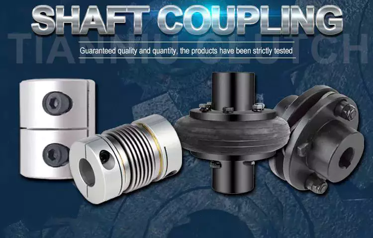
A coupling is a device that connects two shafts together. It transmits power from one end to another and is used for joining rotating equipment. A coupling is flexible and can accommodate a certain amount of end movement and misalignment. This allows for more flexibility in applications. Various types of couplings are available, and each one serves a specific purpose.
Shaft couplings
There are many types of shaft couplings, and they are used in a wide range of applications. The type you need depends on the torque, speed, and horsepower you need, as well as the size of the shaft and its spatial limitations. You may also need to consider whether the coupling will accommodate misalignment.
Some shaft couplings are flexible, while others are rigid. Flexible couplings can accommodate up to two degrees of misalignment. They are available in different materials, including aluminum, stainless steel, and titanium. They can also be known by different names, depending on the industry. Some couplings can also be used in a single or multiple-shaft application.
The first type of shaft coupling is a rigid coupling, which consists of two parts that fit together tightly around the shafts. These couplings are designed to have more flexibility than sleeved models, and they can be used on fixed shafts as well. The flanged coupling, on the other hand, is designed for heavy loads and is made of two perpendicular flanges. The flanges are large enough to accommodate screws and are generally used with heavy-duty applications.
CZPT shaft couplings are a great choice if you’re looking for a shaft coupling that delivers high performance, durability, and low cost. These metal disc-style couplings provide low backlash and high torsional stiffness. Their high misalignment tolerance reduces reaction loads on connected components, which makes them ideal for high-speed precision applications. Available in single and double-disc models, they have torque ratings of up to 2,200 in-lbs. (250N) and are available in fourteen sizes.
When using shaft couplings, it is important to choose the right type for your application. Backlash can cause a shaft coupling to break or become unusable. In order to prevent this from happening, you should replace worn or loose parts, and ensure that the hub and key are evenly positioned with the shaft. If you’re using a shaft coupling in a motion-control system, it is important to keep the torque level consistent.
Flexible couplings
Flexible couplings are a type of coupling used to connect two shafts. They are made of rubber or plastic and allow for axial movement of the connected equipment. They do not require lubrication and are resistant to fatigue failure. Flexible couplings are useful for a number of applications. A common type of flexible coupling is the gear coupling, which has gear teeth inside its sleeve. Another type of flexible coupling is the metallic membrane coupling. A metallic membrane coupling is flexible due to flexing metallic discs.
One major disadvantage of flexible couplings is their inability to fit certain types of pipe. This is because most couplings need to be stretched to fit the pipe. This problem is often the result of a change in pipe technology. Traditionally, drain and soil pipe is made of ductile iron or cast iron. Today, most pipes are made of PVC, which has a larger outside diameter than either cast or ductile iron. Because of these changes in pipe technology, many coupling manufacturers have not updated their mold sizing.
Flexible couplings can be either metallic, elastomeric, or a combination of the three. While there are some common characteristics of each type, you should always consider the tradeoffs of each type before choosing one. Generally, the most important considerations when selecting a flexible coupling are torque, misalignment, and ease of assembly and maintenance.
Flexible couplings are used in a wide range of industries. They are useful for connecting two pipes to ensure torque transfer. Although the types available are different, these are the most adaptable couplings in the market. They can withstand movement, vibration, and bending without causing any damage to the piping.
Clutch couplings
A clutch coupling connects two rotating shafts by friction. The clutch engages power when the engine is running, disengaging power when the brake is applied. Clutch couplings are used in applications where the speed of a machine is variable or where continuous service is required. The clutch can transmit power, torque, and axial force.
Clutch couplings come in a variety of styles and configurations. Some couplings are flexible, while others are rigid. Flexible couplings are available in a variety of materials, including stainless steel and aluminum. Some couplings also have a non-backlash design, which helps compensate for misalignment.
Clutch couplings may be synchronous or asynchronous. Synchronous couplings engage and disengage automatically when the driven machine exceeds its output speed. These couplings are synchronized by a synchronizing mechanism. When the output speed is exceeded, the synchronizing mechanism initiates the engagement process. The synchronizing mechanism does not engage or disengage when the output speed drops.
High speed clutches are available from a variety of manufacturers. Some manufacturers offer OEM assembly, repair services, and third-party logistics. These manufacturers serve the automotive, chemical, food, and wood industries, as well as the oilfield and material handling industries. Custom clutches can be manufactured for specific applications and can be fitted with additional features, such as precision machined teeth or keyway slots and grooves.
Couplings are available in PCE, C/T, and metric bores. Typically, the size of the input and output shafts will determine which type of coupling is needed. In addition, clutches may be configured for intermediate or high speeds, depending on the required torque.
Clamped couplings
Clamped couplings are commonly used in a variety of industries. They can be used in medical equipment, dental equipment, military equipment, laboratory equipment, and in precision industrial controls. They are available in a wide variety of sizes and keyways. This type of coupling offers a number of advantages, including ease of installation and quick and easy replacement.
A clamp coupling connects two parts by compressing them together. The clamping elements can be formed in a variety of ways, but they all have a gap between their surfaces. This friction squeezes the two parts together, much like pulling two rubber gloves apart. This type of coupling is also useful for joining two hoses or piping units.
Clamped couplings are designed with a single or double clamping shaft. The clamping parts are mounted in two halves and are held together by eight socket head cap screws. They offer high torque capacity and require little installation space. Their high rigidity ensures good positioning accuracy, making them ideal for dynamic drives. In addition, they are wear-free and offer simple radial assembly.
The invention relates to a method and system for clamping pipes to a tank vessel. This invention also relates to a method of loading and unloading tank vessels. The method can be used in oil production platforms and other platforms. A single point mooring method is also used in oil production platforms.
Clamped couplings can also be flexible. They can join two shafts together while allowing a small amount of end movement and misalignment. These couplings may also be used in the assembly of motors and gearboxes.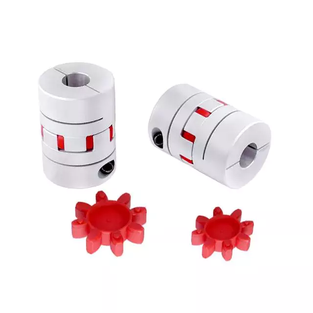
CZPT’s coupling
CZPT couplings are designed to be flexible, allowing them to accommodate misaligned shafts and transmit torque in either direction. They are made with three discs, two hubs, and a center that are arranged with grooves and fins. These features allow for two degrees of freedom during assembly, and can accommodate misalignment of up to 5% of the shaft diameter.
CZPT couplings have many uses. For example, they can be used to join two parallel coaxial rotating shafts. Their ability to transmit torque at the same rotation mechanism and speed makes them ideal for applications where electrical currents may be a problem. Because the couplings are not made of metal, they are electrically isolated. Designers should test their couplings during the prototype stage to ensure they are working properly.
The CZPT coupling consists of two hubs with one slot on each. An intermediate disk is located between the two hubs. The discs are used to reduce or prevent wear on other machine parts. CZPT couplings are inexpensive and easy to replace. They also have electrical insulation, which makes them easy to repair or replace.
CZPT couplings are a popular choice for stepper motor-driven positioning stages. The plastic center disc offers electrical isolation and absorbs shocks from frequent start/stops. These couplings are available in through-hub and blind-bore styles and can be installed in many applications.
CZPT couplings also allow for small degrees of shaft misalignment. This allows them to function in systems where shaft access is limited. They are easily removed without tools.

editor by CX 2023-05-22
China Densen Customized Jm170 Flexible Disc Coupling, Steel Shaft Couplings, Carbon Steel Material Coupling coupling devices
Solution Description
Densen tailored JM170 adaptable disc coupling,steel shaft couplings,carbon steel materials coupling
| Merchandise Identify | Densen custom-made JM170 adaptable disc coupling,metal shaft couplings,carbon metal material coupling |
| DN mm | 170mm |
| Rated Torque | 1000 N·m |
| Max Allowalbe Velocity | 6700RPM |
| Weight | 19.9Kg |
| Material | 45# Metal+Stainless metal(Diaphragm) |
| Software | Broadly used in metallurgy, mining, engineering and other fields. |
|
/ Piece | |
3 Pieces (Min. Order) |
###
| Standard Or Nonstandard: | Standard |
|---|---|
| Bore Diameter: | 170mm |
| Speed: | 6700rpm |
| Material: | 45# Steel+Stainless Steel(Diaphragm) |
| Application: | Widely Used in Metallurgy, Mining, Engineering and |
| Transport Package: | Standard Export Wooden Box |
###
| Samples: |
US$ 450/Piece
1 Piece(Min.Order) |
|---|
###
| Customization: |
|---|
###
| Product Name | Densen customized JM170 flexible disc coupling,steel shaft couplings,carbon steel material coupling |
| DN mm | 170mm |
| Rated Torque | 1000 N·m |
| Max Allowalbe Speed | 6700RPM |
| Weight | 19.9Kg |
| Material | 45# Steel+Stainless steel(Diaphragm) |
| Application | Widely used in metallurgy, mining, engineering and other fields. |
What Is a Coupling?
A coupling is a device used to connect two shafts. It transmits power between them and allows for some misalignment or end movement. There are several types of couplings. The most common ones are gear couplings and planetary couplings. However, there are many others as well.
Transfer of energy
Energy coupling is a process by which two biological reactions are linked by sharing energy. The energy released during one reaction can be used to drive the second. It is a very useful mechanism that synchronizes two biological systems. All cells have two types of reactions, exergonic and endergonic, and they are connected through energy coupling.
This process is important for a number of reasons. The first is that it allows the exchange of electrons and their energy. In a single molecule, this energy transfer involves the exchange of two electrons of different energy and spin. This exchange occurs because of the overlap interaction of two MOs.
Secondly, it is possible to achieve quadratic coupling. This is a phenomenon that occurs in circular membrane resonators when the system is statically deflected. This phenomenon has been gaining a great deal of interest as a mechanism for stronger coupling. If this mechanism is employed in a physical system, energy can be transferred on a nanometer scale.
The magnetic field is another important factor that affects the exchange of energy between semiconductor QWs. A strong magnetic field controls the strength of the coupling and the energy order of the exciton. The magnetic field can also influence the direction of polariton-mediated energy transfer. This mechanism is very promising for controlling the routing of excitation in a semiconductor.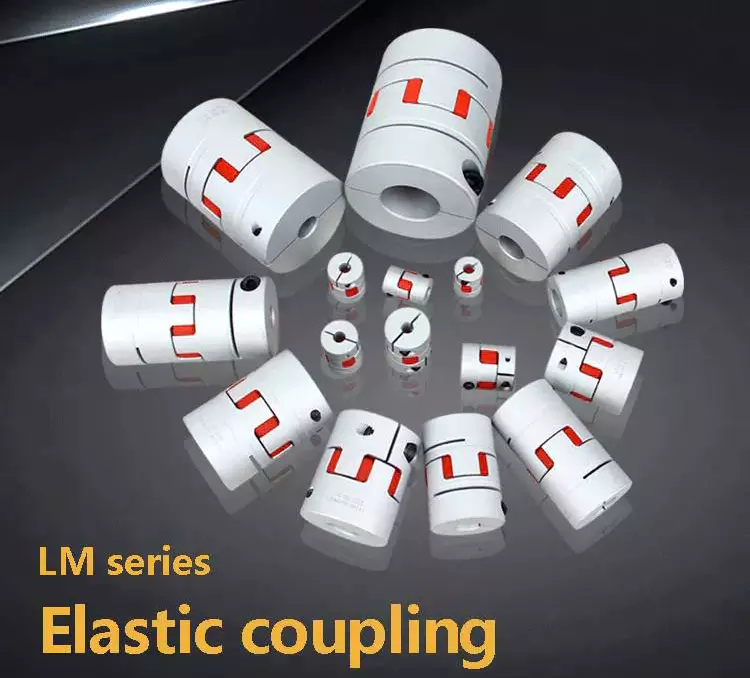
Functions
Couplings play a variety of functions, including transferring power, compensating for misalignment, and absorbing shock. These functions depend on the type of shaft being coupled. There are four basic types: angular, parallel, and symmetrical. In many cases, coupling is necessary to accommodate misalignment.
Couplings are mechanical devices that join two rotating pieces of equipment. They are used to transfer power and allow for a small degree of end-to-end misalignment. This allows them to be used in many different applications, such as the transmission from the gearbox to the differential in an automobile. In addition, couplings can be used to transfer power to spindles.
Types
There are two main types of couplings: rigid and flexible. Rigid couplings are designed to prevent relative motion between the two shafts and are suitable for applications where precise alignment is required. However, high stresses in the case of significant misalignment can cause early failure of the coupling. Flexible couplings, on the other hand, allow for misalignment and allow for torque transmission.
A software application may exhibit different types of coupling. The first type involves the use of data. This means that one module may use data from another module for its operation. A good example of data coupling is the inheritance of an object. In a software application, one module can use another module’s data and parameters.
Another type of coupling is a rigid sleeve coupling. This type of coupling has a pipe with a bore that is finished to a specified tolerance. The pipe contains two threaded holes for transmitting torque. The sleeve is secured by a gib head key. This type of coupling may be used in applications where a couple of shafts are close together.
Other types of coupling include common and external. Common coupling occurs when two modules share global data and communication protocols. This type of coupling can lead to uncontrollable error propagation and unforeseen side effects when changes are made to the system. External coupling, on the other hand, involves two modules sharing an external device interface or communication protocol. Both types of coupling involve a shared code structure and depend on the external modules or hardware.
Mechanical couplings are essential in power transmission. They connect rotating shafts and can either be rigid or flexible, depending on the accuracy required. These couplings are used in pumps, compressors, motors, and generators to transmit power and torque. In addition to transferring power, couplings can also prevent torque overload.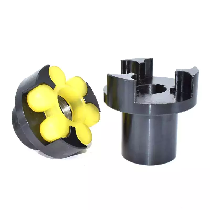
Applications
Different coupling styles are ideal for different applications, and they have different characteristics that influence the coupling’s reliability during operation. These characteristics include stiffness, misalignment capability, ease of installation and maintenance, inherent balance, and speed capability. Selecting the right coupling style for a particular application is essential to minimize performance problems and maximize utility.
It is important to know the requirements for the coupling you choose before you start shopping. A proper selection process takes into account several design criteria, including torque and rpm, acoustic signals, and environmental factors. Once you’ve identified these parameters, you can select the best coupling for the job.
A gear coupling provides a mechanical connection between two rotating shafts. These couplings use gear mesh to transmit torque and power between two shafts. They’re typically used on large industrial machines, but they can also be used in smaller motion control systems. In smaller systems, a zero-backlash coupling design is ideal.
Another type of coupling is the flange coupling. These are easy to manufacture. Their design is similar to a sleeve coupling. But unlike a sleeve coupling, a flange coupling features a keyway on one side and two threaded holes on the other. These couplings are used in medium-duty industrial applications.
Besides being useful for power transmission, couplings can also prevent machine vibration. If vibration occurs in a machine, it can cause it to deviate from its predetermined position, or damage the motor. Couplings, however, help prevent this by absorbing the vibration and shock and preventing damage to expensive parts.
Couplings are heavily used in the industrial machinery and electrical industries. They provide the necessary rotation mechanism required by machinery and other equipment. Coupling suppliers can help customers find the right coupling for a specific application.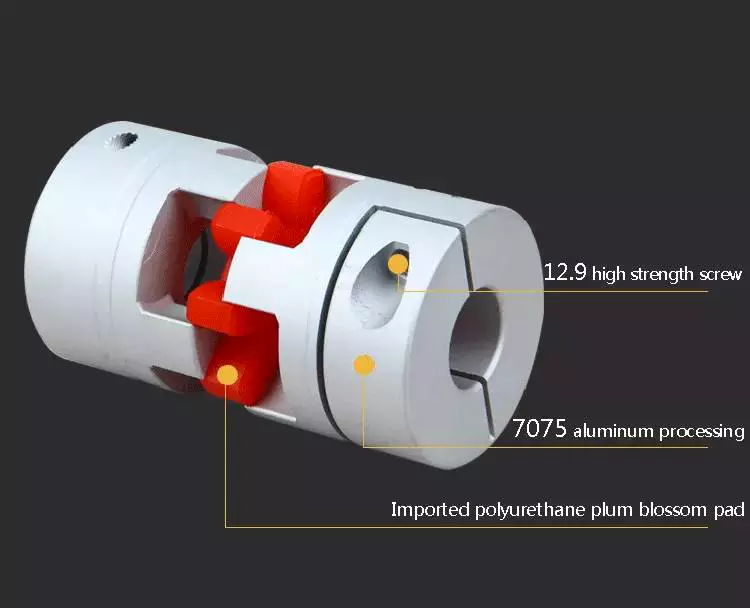
Criteria for selecting a coupling
When selecting a coupling for a specific application, there are a number of different factors to consider. These factors vary greatly, as do operating conditions, so selecting the best coupling for your system can be challenging. Some of these factors include horsepower, torque, and speed. You also need to consider the size of the shafts and the geometry of the equipment. Space restrictions and maintenance and installation requirements should also be taken into account. Other considerations can be specific to your system, such as the need for reversing.
First, determine what size coupling you need. The coupling’s size should be able to handle the torque required by the application. In addition, determine the interface connection, such as straight or tapered keyed shafts. Some couplings also feature integral flange connections.
During the specification process, be sure to specify which materials the coupling will be made of. This is important because the material will dictate most of its performance characteristics. Most couplings are made of stainless steel or aluminum, but you can also find ones made of Delrin, titanium, or other engineering-grade materials.
One of the most important factors to consider when selecting a coupling is its torque capability. If the torque rating is not adequate, the coupling can be damaged or break easily. Torque is a major factor in coupling selection, but it is often underestimated. In order to ensure maximum coupling performance, you should also take into consideration the size of the shafts and hubs.
In some cases, a coupling will need lubrication throughout its lifecycle. It may need to be lubricated every six months or even once a year. But there are couplings available that require no lubrication at all. An RBI flexible coupling by CZPT is one such example. Using a coupling of this kind can immediately cut down your total cost of ownership.

editor by CX 2023-03-31