Product Description
Product Description
Coupling Deatails
Name: High precision plum blossom
coupling Model: LM-Material: Aviation Aluminum Alloy
Working temperature: -40 ° C ~ 100 ° C
Support customization: Factory direct sales support customization.
Features:
1.Intermediate Elastomer Connection-Absorbs vibration, compensates for radial, angular, and axial 2.misalignment
3.Oil resistance and electrical insulation
4.Clockwise and counterclockwise rotation characteristics are identical-there are 3 different hardness 5.elastomer
6.Fixation by clamping screw.
|
Model parameter |
ΦD |
L |
LF |
LP |
F |
M |
Tightening screw torque |
|
(N.M) |
|||||||
|
GF-14X22 |
14 |
22 |
14.3 |
6.6 |
3.8 |
M 3 |
0.7 |
|
GF-20X25 |
20 |
25 |
16.7 |
8.6 |
4 |
M 3 |
0.7 |
|
GF-20X30 |
20 |
30 |
19.25 |
8.6 |
5.3 |
M 4 |
1.7 |
|
GF-25X30 |
25 |
30 |
20.82 |
11.6 |
5.6 |
M 4 |
1.7 |
|
GF-25X34 |
25 |
34 |
22.82 |
11.6 |
5.6 |
M 4 |
1.7 |
|
GF-30X35 |
30 |
35 |
23 |
11.5 |
5.75 |
M 4 |
1.7 |
|
GF-30X40 |
30 |
40 |
25.6 |
11.5 |
10 |
M 4 |
1.7 |
|
GF-40X50 |
40 |
50 |
32.1 |
14.5 |
10 |
M 5 |
4 |
|
GF-40X55 |
40 |
55 |
34.5 |
14.5 |
10 |
M 5 |
4 |
|
GF-40X66 |
40 |
66 |
40 |
14.5 |
12.75 |
M 5 |
4 |
|
GF-55X49 |
55 |
49 |
32 |
16.1 |
13.5 |
M 6 |
8.4 |
|
GF-55X78 |
55 |
78 |
46.4 |
16.1 |
15.5 |
M 6 |
8.4 |
|
GF-65X80 |
65 |
80 |
48.5 |
17.3 |
18.1 |
M 8 |
10.5 |
|
GF-65X90 |
65 |
90 |
53.5 |
17.3 |
18.1 |
M 8 |
10.5 |
Product Parameters
Detailed Photos
/* January 22, 2571 19:08:37 */!function(){function s(e,r){var a,o={};try{e&&e.split(“,”).forEach(function(e,t){e&&(a=e.match(/(.*?):(.*)$/))&&1

Specific Safety Precautions When Working with Shaft Couplings
Working with shaft couplings involves handling rotating machinery and mechanical components. To ensure the safety of personnel and prevent accidents, specific safety precautions should be followed during installation, maintenance, and operation:
1. Lockout-Tagout (LOTO):
Prior to any work on machinery involving couplings, implement a lockout-tagout procedure to isolate the equipment from its power source. This ensures that the machinery cannot be accidentally energized during maintenance or repair, protecting workers from potential hazards.
2. Personal Protective Equipment (PPE):
Always wear appropriate personal protective equipment (PPE), including safety goggles, gloves, and appropriate clothing, when working with shaft couplings. PPE helps protect against potential hazards such as flying debris, sharp edges, or contact with moving parts.
3. Proper Training and Supervision:
Only trained and authorized personnel should work with shaft couplings. Ensure that workers have the necessary knowledge and experience to handle the equipment safely. Adequate supervision may be required, especially for less-experienced personnel.
4. Inspection and Maintenance:
Regularly inspect shaft couplings and associated components for signs of wear, damage, or misalignment. Address any issues promptly to prevent equipment failure and potential accidents.
5. Follow Manufacturer’s Guidelines:
Adhere to the manufacturer’s instructions and guidelines for installation, operation, and maintenance of the specific coupling model. Improper use or deviation from recommended procedures may compromise safety and void warranties.
6. Avoid Overloading:
Do not exceed the torque and speed limits specified by the coupling manufacturer. Overloading a coupling can lead to premature failure and pose safety risks to operators and nearby equipment.
7. Shaft Guards and Enclosures:
Install appropriate guards and enclosures to prevent accidental contact with rotating shafts and couplings. These safety measures help reduce the risk of entanglement and injuries.
8. Zero Energy State:
Ensure that all stored energy in the equipment, such as compressed air or hydraulic pressure, is released and the equipment is in a zero energy state before starting work.
9. Avoid Loose Clothing and Jewelry:
Remove or secure loose clothing, jewelry, and other items that could get caught in moving parts.
10. Maintain a Clean Work Area:
Keep the work area clean and free from clutter to avoid tripping hazards and facilitate safe movement around the machinery.
By following these safety precautions, personnel can minimize the risks associated with working with shaft couplings and create a safer working environment for everyone involved.
“`
Can Shaft Couplings Handle Reversing Loads and Shock Loads Effectively?
Yes, shaft couplings are designed to handle both reversing loads and shock loads effectively, but the capability depends on the specific type of coupling and its design.
Reversing Loads:
Many shaft couplings, such as elastomeric couplings, gear couplings, and grid couplings, can handle reversing loads without any issue. Reversing loads occur when the direction of the torque changes periodically, causing the shafts to rotate in opposite directions. The flexibility of elastomeric couplings and the sturdy design of gear and grid couplings allow them to accommodate these reversing loads while maintaining reliable torque transmission.
Shock Loads:
Shock loads are sudden and high-magnitude forces that occur during start-up, sudden stops, or impact events. Shaft couplings with shock-absorbing features, such as elastomeric couplings and grid couplings, excel at handling shock loads. The elastomeric material in elastomeric couplings and the grid element in grid couplings act as shock absorbers, reducing the impact on the connected equipment and minimizing the risk of damage to the coupling itself.
It’s essential to select the appropriate coupling type based on the specific application’s requirements, including the magnitude and frequency of reversing loads and shock loads. Some couplings may have limitations on the amount of shock load they can handle, so it’s crucial to refer to the manufacturer’s specifications and guidelines for proper coupling selection.
In heavy-duty applications with high reversing loads and shock loads, it may be necessary to consider specialized couplings designed explicitly for such conditions, like disc couplings or fluid couplings, which can offer even better performance in handling these challenging load conditions.
“`
Can a Damaged Shaft Coupling Lead to Equipment Failure and Downtime?
Yes, a damaged shaft coupling can lead to equipment failure and downtime in mechanical power transmission systems. Shaft couplings play a critical role in connecting rotating shafts and transmitting power between them. When a coupling becomes damaged or fails to function properly, several negative consequences can arise:
1. Misalignment Issues:
A damaged coupling may no longer be able to compensate for misalignments between the connected shafts. Misalignment can cause excessive vibration, increased wear, and premature failure of bearings and other connected components. Over time, these issues can lead to equipment breakdown and unplanned downtime.
2. Vibration and Shock Loads:
Without the damping properties of a functional coupling, vibrations and shock loads from the driven equipment can transmit directly to the driving shaft and other parts of the system. Excessive vibrations can lead to fatigue failure, cracking, and damage to the equipment, resulting in reduced operational efficiency and increased downtime.
3. Overloading and Torque Transmission:
A damaged coupling may not effectively transmit the required torque between the driving and driven shafts. In applications where the coupling is a safety device (e.g., shear pin couplings), failure to disengage during overloading situations can lead to equipment overload and damage.
4. Increased Wear and Tear:
A damaged coupling can lead to increased wear on other parts of the system. Components such as bearings, seals, and gears may experience higher stress and wear, reducing their lifespan and increasing the likelihood of breakdowns.
5. Reduced System Reliability:
A functional shaft coupling contributes to the overall reliability of the mechanical system. A damaged coupling compromises this reliability, making the system more prone to failures and unplanned maintenance.
6. Downtime and Production Loss:
When a shaft coupling fails, it often results in unscheduled downtime for repairs or replacement. Downtime can be costly for industries that rely on continuous production processes and can lead to production losses and missed delivery deadlines.
7. Safety Hazards:
In certain applications, such as heavy machinery or industrial equipment, a damaged coupling can create safety hazards for workers and surrounding equipment. Sudden failures or uncontrolled movements may pose risks to personnel and property.
Regular inspection, maintenance, and prompt replacement of damaged shaft couplings are essential to prevent equipment failure, minimize downtime, and ensure safe and efficient operation of mechanical systems. It is crucial to address any signs of coupling wear or damage immediately to avoid potential catastrophic failures and costly disruptions to operations.
“`

editor by CX 2024-05-10
China wholesaler CNC Aluminum Elastic Rubber Spider Jaw Shaft Coupler GF14*22 20*25 25*30 40*50 Shaft Flexible Coupling Ball Screw Plum Coupling
Product Description
Product Description
Coupling Deatails
Name: High precision plum blossom
coupling Model: LM-Material: Aviation Aluminum Alloy
Working temperature: -40 ° C ~ 100 ° C
Support customization: Factory direct sales support customization.
Features:
1.Intermediate Elastomer Connection-Absorbs vibration, compensates for radial, angular, and axial 2.misalignment
3.Oil resistance and electrical insulation
4.Clockwise and counterclockwise rotation characteristics are identical-there are 3 different hardness 5.elastomer
6.Fixation by clamping screw.
|
Model parameter |
ΦD |
L |
LF |
LP |
F |
M |
Tightening screw torque |
|
(N.M) |
|||||||
|
GF-14X22 |
14 |
22 |
14.3 |
6.6 |
3.8 |
M 3 |
0.7 |
|
GF-20X25 |
20 |
25 |
16.7 |
8.6 |
4 |
M 3 |
0.7 |
|
GF-20X30 |
20 |
30 |
19.25 |
8.6 |
5.3 |
M 4 |
1.7 |
|
GF-25X30 |
25 |
30 |
20.82 |
11.6 |
5.6 |
M 4 |
1.7 |
|
GF-25X34 |
25 |
34 |
22.82 |
11.6 |
5.6 |
M 4 |
1.7 |
|
GF-30X35 |
30 |
35 |
23 |
11.5 |
5.75 |
M 4 |
1.7 |
|
GF-30X40 |
30 |
40 |
25.6 |
11.5 |
10 |
M 4 |
1.7 |
|
GF-40X50 |
40 |
50 |
32.1 |
14.5 |
10 |
M 5 |
4 |
|
GF-40X55 |
40 |
55 |
34.5 |
14.5 |
10 |
M 5 |
4 |
|
GF-40X66 |
40 |
66 |
40 |
14.5 |
12.75 |
M 5 |
4 |
|
GF-55X49 |
55 |
49 |
32 |
16.1 |
13.5 |
M 6 |
8.4 |
|
GF-55X78 |
55 |
78 |
46.4 |
16.1 |
15.5 |
M 6 |
8.4 |
|
GF-65X80 |
65 |
80 |
48.5 |
17.3 |
18.1 |
M 8 |
10.5 |
|
GF-65X90 |
65 |
90 |
53.5 |
17.3 |
18.1 |
M 8 |
10.5 |
Product Parameters
Detailed Photos
/* January 22, 2571 19:08:37 */!function(){function s(e,r){var a,o={};try{e&&e.split(“,”).forEach(function(e,t){e&&(a=e.match(/(.*?):(.*)$/))&&1
Exploring the Use of Elastomeric Materials in Flexible Shaft Couplings
Elastomeric materials play a crucial role in the design and function of flexible shaft couplings. These materials, commonly known as elastomers, are rubber-like substances that exhibit high elasticity and flexibility. They are widely used in various types of flexible couplings due to their unique properties and benefits:
1. Damping and Vibration Absorption:
Elastomeric materials have excellent damping characteristics, meaning they can absorb and dissipate vibrations and shocks. This property is particularly useful in applications where vibration control is essential to protect sensitive equipment and improve overall system performance.
2. Misalignment Compensation:
Flexible shaft couplings with elastomeric elements can accommodate different types of misalignments, including angular, parallel, and radial misalignments. The elasticity of the material allows for limited movement between the shafts while still transmitting torque efficiently.
3. Torsional Flexibility:
Elastomers offer torsional flexibility, which allows them to twist and deform under torque loads. This feature helps to minimize torsional stresses and torsional backlash, making them suitable for applications requiring precise motion control.
4. Shock and Impact Resistance:
Due to their high resilience, elastomers can withstand sudden shocks and impacts without permanent deformation. This property makes them ideal for use in machinery subjected to varying loads or rapid changes in torque.
5. No Lubrication Requirement:
Elastomeric couplings are often maintenance-free because the elastomer material does not require additional lubrication. This reduces maintenance costs and simplifies the overall system upkeep.
6. Electric Isolation:
In certain applications, elastomeric materials can provide electrical isolation between the driving and driven components. This can help prevent the transmission of electrical currents or static charges through the coupling.
7. Corrosion Resistance:
Many elastomers used in couplings are resistant to corrosion, making them suitable for use in challenging environments where exposure to chemicals or moisture is a concern.
8. Easy Installation:
Elastomeric couplings are often designed for ease of installation and replacement. Their flexibility allows for simple and quick assembly onto the shafts without the need for special tools or complex procedures.
Given these advantages, elastomeric materials are popular choices for various flexible shaft couplings, including jaw couplings, tire couplings, and spider couplings. However, it is essential to select the right elastomer material based on the specific application requirements, such as temperature range, chemical compatibility, and torque capacity.
“`
Temperature and Speed Limits for Different Shaft Coupling Types
The temperature and speed limits of shaft couplings vary depending on the materials and design of the coupling. Manufacturers provide specific guidelines and ratings for each coupling type. Below are general temperature and speed limits for some common shaft coupling types:
1. Elastomeric Couplings:
Elastomeric couplings, such as jaw couplings and tire couplings, typically have temperature limits ranging from -40°C to 100°C (-40°F to 212°F). The speed limits for elastomeric couplings are generally up to 5,000 RPM, but some designs may allow higher speeds.
2. Metallic Couplings:
Metallic couplings, like gear couplings and disc couplings, can handle a wider temperature range, typically from -50°C to 200°C (-58°F to 392°F). The speed limits for metallic couplings vary based on the size and design, but they can range from 3,000 RPM to over 10,000 RPM.
3. Grid Couplings:
Grid couplings have temperature limits similar to metallic couplings, ranging from -50°C to 200°C (-58°F to 392°F). The speed limits for grid couplings are typically in the range of 3,000 to 5,000 RPM.
4. Oldham Couplings:
Oldham couplings usually have temperature limits from -30°C to 100°C (-22°F to 212°F) and speed limits ranging from 1,000 to 5,000 RPM.
5. Beam Couplings:
Beam couplings generally have temperature limits from -40°C to 120°C (-40°F to 248°F) and speed limits between 5,000 to 10,000 RPM.
6. Fluid Couplings:
Fluid couplings are suitable for a wide range of temperatures, often from -50°C to 300°C (-58°F to 572°F). The speed limits depend on the size and design of the fluid coupling but can extend to several thousand RPM.
It’s important to note that these are general guidelines, and the actual temperature and speed limits may vary based on the specific coupling manufacturer, material quality, and application requirements. Always refer to the manufacturer’s documentation and technical specifications for accurate and up-to-date temperature and speed limits for a particular shaft coupling model.
“`
Best Practices for Installing a Shaft Coupling for Optimal Performance
Proper installation of a shaft coupling is crucial for ensuring optimal performance and preventing premature wear or failure. Follow these best practices to install a shaft coupling correctly:
1. Shaft Alignment:
Ensure that both the driving and driven shafts are properly aligned before installing the coupling. Misalignment can lead to increased stress on the coupling and other connected components, reducing efficiency and causing premature wear. Use alignment tools, such as dial indicators or laser alignment systems, to achieve accurate shaft alignment.
2. Cleanliness:
Before installation, clean the shaft ends and the coupling bore thoroughly. Remove any dirt, debris, or residue that could interfere with the coupling’s fit or cause misalignment.
3. Lubrication:
Apply the recommended lubricant to the coupling’s contact surfaces, such as the bore and shaft ends. Proper lubrication ensures smooth installation and reduces friction during operation.
4. Correct Fit:
Ensure that the coupling is the correct size and type for the application. Use couplings with the appropriate torque and speed ratings to match the equipment’s requirements.
5. Fastening:
Use the recommended fastening methods, such as set screws or keyways, to securely attach the coupling to the shafts. Make sure the fasteners are tightened to the manufacturer’s specifications to prevent loosening during operation.
6. Spacer or Adapter:
If required, use a spacer or adapter to properly position the coupling on the shafts and maintain the desired distance between the driving and driven components.
7. Avoid Shaft Damage:
Be careful during installation to avoid damaging the shaft ends, especially when using set screws or other fastening methods. Shaft damage can lead to stress concentrations and eventual failure.
8. Check Runout:
After installation, check the coupling’s runout using a dial indicator to ensure that it rotates smoothly and without wobbling. Excessive runout can indicate misalignment or improper fit.
9. Periodic Inspection:
Regularly inspect the coupling and its components for signs of wear, misalignment, or damage. Perform routine maintenance as recommended by the manufacturer to prevent issues from worsening over time.
10. Follow Manufacturer’s Guidelines:
Always follow the manufacturer’s installation instructions and guidelines. Different types of couplings may have specific installation requirements that need to be adhered to for optimal performance and safety.
By following these best practices, you can ensure that your shaft coupling is installed correctly, maximizing its efficiency and reliability in your mechanical power transmission system.
“`
editor by CX 2024-05-09
China Hot selling CNC Aluminum Elastic Rubber Spider Jaw Shaft Coupler GF14*22 20*25 25*30 40*50 Shaft Flexible Coupling Ball Screw Plum Coupling
Product Description
Product Description
Coupling Deatails
Name: High precision plum blossom
coupling Model: LM-Material: Aviation Aluminum Alloy
Working temperature: -40 ° C ~ 100 ° C
Support customization: Factory direct sales support customization.
Features:
1.Intermediate Elastomer Connection-Absorbs vibration, compensates for radial, angular, and axial 2.misalignment
3.Oil resistance and electrical insulation
4.Clockwise and counterclockwise rotation characteristics are identical-there are 3 different hardness 5.elastomer
6.Fixation by clamping screw.
|
Model parameter |
ΦD |
L |
LF |
LP |
F |
M |
Tightening screw torque |
|
(N.M) |
|||||||
|
GF-14X22 |
14 |
22 |
14.3 |
6.6 |
3.8 |
M 3 |
0.7 |
|
GF-20X25 |
20 |
25 |
16.7 |
8.6 |
4 |
M 3 |
0.7 |
|
GF-20X30 |
20 |
30 |
19.25 |
8.6 |
5.3 |
M 4 |
1.7 |
|
GF-25X30 |
25 |
30 |
20.82 |
11.6 |
5.6 |
M 4 |
1.7 |
|
GF-25X34 |
25 |
34 |
22.82 |
11.6 |
5.6 |
M 4 |
1.7 |
|
GF-30X35 |
30 |
35 |
23 |
11.5 |
5.75 |
M 4 |
1.7 |
|
GF-30X40 |
30 |
40 |
25.6 |
11.5 |
10 |
M 4 |
1.7 |
|
GF-40X50 |
40 |
50 |
32.1 |
14.5 |
10 |
M 5 |
4 |
|
GF-40X55 |
40 |
55 |
34.5 |
14.5 |
10 |
M 5 |
4 |
|
GF-40X66 |
40 |
66 |
40 |
14.5 |
12.75 |
M 5 |
4 |
|
GF-55X49 |
55 |
49 |
32 |
16.1 |
13.5 |
M 6 |
8.4 |
|
GF-55X78 |
55 |
78 |
46.4 |
16.1 |
15.5 |
M 6 |
8.4 |
|
GF-65X80 |
65 |
80 |
48.5 |
17.3 |
18.1 |
M 8 |
10.5 |
|
GF-65X90 |
65 |
90 |
53.5 |
17.3 |
18.1 |
M 8 |
10.5 |
Product Parameters
Detailed Photos
/* January 22, 2571 19:08:37 */!function(){function s(e,r){var a,o={};try{e&&e.split(“,”).forEach(function(e,t){e&&(a=e.match(/(.*?):(.*)$/))&&1

Can Shaft Couplings Compensate for Angular, Parallel, and Axial Misalignments?
Yes, shaft couplings are designed to compensate for different types of misalignments between rotating shafts in mechanical power transmission systems. They can handle the following types of misalignments:
- Angular Misalignment: This occurs when the shafts are not parallel and have an angle between them. Flexible couplings, such as elastomeric, beam, or Oldham couplings, can accommodate angular misalignments by allowing slight angular movement between the shafts while transmitting torque.
- Parallel Misalignment: This happens when the shafts are not collinear, resulting in axial displacement. Flexible couplings with lateral flexibility, like elastomeric or bellows couplings, can handle parallel misalignment by allowing limited lateral movement between the shafts.
- Radial Misalignment: Radial misalignment occurs when the shafts have lateral displacement but remain parallel. Flexible couplings, such as jaw or grid couplings, can absorb radial misalignment by permitting some lateral deflection while transmitting torque.
It is essential to note that while shaft couplings can compensate for misalignments to some extent, they do have their limits. The magnitude of misalignment they can handle depends on the type and design of the coupling. Exceeding the specified misalignment capabilities of a coupling can lead to premature wear, reduced efficiency, and possible coupling failure.
Therefore, when selecting a shaft coupling for an application, it is crucial to consider the expected misalignment and choose a coupling that can accommodate the anticipated misalignment range. Additionally, maintaining proper alignment through regular maintenance and periodic inspections is essential to ensure the coupling’s optimal performance and extend its service life.
“`
Can Shaft Couplings Handle Reversing Loads and Shock Loads Effectively?
Yes, shaft couplings are designed to handle both reversing loads and shock loads effectively, but the capability depends on the specific type of coupling and its design.
Reversing Loads:
Many shaft couplings, such as elastomeric couplings, gear couplings, and grid couplings, can handle reversing loads without any issue. Reversing loads occur when the direction of the torque changes periodically, causing the shafts to rotate in opposite directions. The flexibility of elastomeric couplings and the sturdy design of gear and grid couplings allow them to accommodate these reversing loads while maintaining reliable torque transmission.
Shock Loads:
Shock loads are sudden and high-magnitude forces that occur during start-up, sudden stops, or impact events. Shaft couplings with shock-absorbing features, such as elastomeric couplings and grid couplings, excel at handling shock loads. The elastomeric material in elastomeric couplings and the grid element in grid couplings act as shock absorbers, reducing the impact on the connected equipment and minimizing the risk of damage to the coupling itself.
It’s essential to select the appropriate coupling type based on the specific application’s requirements, including the magnitude and frequency of reversing loads and shock loads. Some couplings may have limitations on the amount of shock load they can handle, so it’s crucial to refer to the manufacturer’s specifications and guidelines for proper coupling selection.
In heavy-duty applications with high reversing loads and shock loads, it may be necessary to consider specialized couplings designed explicitly for such conditions, like disc couplings or fluid couplings, which can offer even better performance in handling these challenging load conditions.
“`
How Does a Flexible Shaft Coupling Differ from a Rigid Shaft Coupling?
Flexible shaft couplings and rigid shaft couplings are two distinct types of couplings, each designed to serve different purposes in mechanical power transmission. Here are the key differences between the two:
1. Flexibility:
The most significant difference between flexible and rigid shaft couplings is their flexibility. Flexible couplings are designed with elements that can deform or flex to accommodate misalignments between the shafts. This flexibility allows for angular, parallel, and axial misalignments, making them suitable for applications where shafts are not perfectly aligned. In contrast, rigid couplings do not have this flexibility and require precise alignment between the shafts.
2. Misalignment Compensation:
Flexible couplings excel in compensating for misalignments, making them ideal for applications with dynamic conditions or those prone to misalignment due to thermal expansion or vibrations. Rigid couplings, on the other hand, are used in applications where perfect alignment is critical to prevent vibration, wear, and premature failure.
3. Damping Properties:
Flexible couplings, particularly those with elastomeric or flexible elements, offer damping properties, meaning they can absorb and reduce shocks and vibrations. This damping capability helps protect the connected equipment from damage and enhances system reliability. Rigid couplings lack this damping ability and can transmit shocks and vibrations directly between shafts.
4. Torque Transmission:
Both flexible and rigid couplings are capable of transmitting torque from the driving shaft to the driven shaft. However, the torque transmission of flexible couplings can be limited compared to rigid couplings, especially in high-torque applications.
5. Types of Applications:
Flexible couplings find applications in a wide range of industries, especially in situations where misalignment compensation, vibration damping, and shock absorption are essential. They are commonly used in conveyors, pumps, compressors, printing presses, and automation systems. Rigid couplings are used in precision machinery and applications that demand perfect alignment, such as high-speed spindles and certain types of precision equipment.
6. Installation:
Flexible couplings are relatively easier to install due to their ability to accommodate misalignment. On the other hand, rigid couplings require careful alignment during installation to ensure proper functioning and prevent premature wear.
The choice between a flexible and a rigid shaft coupling depends on the specific requirements of the application. If misalignment compensation, damping, and flexibility are critical, a flexible coupling is the preferred choice. If precision alignment and direct torque transmission are essential, a rigid coupling is more suitable.
“`
editor by CX 2024-04-29
China supplier CNC Aluminum Elastic Rubber Spider Jaw Shaft Coupler GF14*22 20*25 25*30 40*50 Shaft Flexible Coupling Ball Screw Plum Coupling
Product Description
Product Description
Coupling Deatails
Name: High precision plum blossom
coupling Model: LM-Material: Aviation Aluminum Alloy
Working temperature: -40 ° C ~ 100 ° C
Support customization: Factory direct sales support customization.
Features:
1.Intermediate Elastomer Connection-Absorbs vibration, compensates for radial, angular, and axial 2.misalignment
3.Oil resistance and electrical insulation
4.Clockwise and counterclockwise rotation characteristics are identical-there are 3 different hardness 5.elastomer
6.Fixation by clamping screw.
|
Model parameter |
ΦD |
L |
LF |
LP |
F |
M |
Tightening screw torque |
|
(N.M) |
|||||||
|
GF-14X22 |
14 |
22 |
14.3 |
6.6 |
3.8 |
M 3 |
0.7 |
|
GF-20X25 |
20 |
25 |
16.7 |
8.6 |
4 |
M 3 |
0.7 |
|
GF-20X30 |
20 |
30 |
19.25 |
8.6 |
5.3 |
M 4 |
1.7 |
|
GF-25X30 |
25 |
30 |
20.82 |
11.6 |
5.6 |
M 4 |
1.7 |
|
GF-25X34 |
25 |
34 |
22.82 |
11.6 |
5.6 |
M 4 |
1.7 |
|
GF-30X35 |
30 |
35 |
23 |
11.5 |
5.75 |
M 4 |
1.7 |
|
GF-30X40 |
30 |
40 |
25.6 |
11.5 |
10 |
M 4 |
1.7 |
|
GF-40X50 |
40 |
50 |
32.1 |
14.5 |
10 |
M 5 |
4 |
|
GF-40X55 |
40 |
55 |
34.5 |
14.5 |
10 |
M 5 |
4 |
|
GF-40X66 |
40 |
66 |
40 |
14.5 |
12.75 |
M 5 |
4 |
|
GF-55X49 |
55 |
49 |
32 |
16.1 |
13.5 |
M 6 |
8.4 |
|
GF-55X78 |
55 |
78 |
46.4 |
16.1 |
15.5 |
M 6 |
8.4 |
|
GF-65X80 |
65 |
80 |
48.5 |
17.3 |
18.1 |
M 8 |
10.5 |
|
GF-65X90 |
65 |
90 |
53.5 |
17.3 |
18.1 |
M 8 |
10.5 |
Product Parameters
Detailed Photos
/* January 22, 2571 19:08:37 */!function(){function s(e,r){var a,o={};try{e&&e.split(“,”).forEach(function(e,t){e&&(a=e.match(/(.*?):(.*)$/))&&1
Specific Safety Precautions When Working with Shaft Couplings
Working with shaft couplings involves handling rotating machinery and mechanical components. To ensure the safety of personnel and prevent accidents, specific safety precautions should be followed during installation, maintenance, and operation:
1. Lockout-Tagout (LOTO):
Prior to any work on machinery involving couplings, implement a lockout-tagout procedure to isolate the equipment from its power source. This ensures that the machinery cannot be accidentally energized during maintenance or repair, protecting workers from potential hazards.
2. Personal Protective Equipment (PPE):
Always wear appropriate personal protective equipment (PPE), including safety goggles, gloves, and appropriate clothing, when working with shaft couplings. PPE helps protect against potential hazards such as flying debris, sharp edges, or contact with moving parts.
3. Proper Training and Supervision:
Only trained and authorized personnel should work with shaft couplings. Ensure that workers have the necessary knowledge and experience to handle the equipment safely. Adequate supervision may be required, especially for less-experienced personnel.
4. Inspection and Maintenance:
Regularly inspect shaft couplings and associated components for signs of wear, damage, or misalignment. Address any issues promptly to prevent equipment failure and potential accidents.
5. Follow Manufacturer’s Guidelines:
Adhere to the manufacturer’s instructions and guidelines for installation, operation, and maintenance of the specific coupling model. Improper use or deviation from recommended procedures may compromise safety and void warranties.
6. Avoid Overloading:
Do not exceed the torque and speed limits specified by the coupling manufacturer. Overloading a coupling can lead to premature failure and pose safety risks to operators and nearby equipment.
7. Shaft Guards and Enclosures:
Install appropriate guards and enclosures to prevent accidental contact with rotating shafts and couplings. These safety measures help reduce the risk of entanglement and injuries.
8. Zero Energy State:
Ensure that all stored energy in the equipment, such as compressed air or hydraulic pressure, is released and the equipment is in a zero energy state before starting work.
9. Avoid Loose Clothing and Jewelry:
Remove or secure loose clothing, jewelry, and other items that could get caught in moving parts.
10. Maintain a Clean Work Area:
Keep the work area clean and free from clutter to avoid tripping hazards and facilitate safe movement around the machinery.
By following these safety precautions, personnel can minimize the risks associated with working with shaft couplings and create a safer working environment for everyone involved.
“`
Comparing Shaft Couplings with Other Types of Couplings in Performance
Shaft couplings are essential components in mechanical power transmission systems, and their performance characteristics vary depending on the coupling type. Let’s compare shaft couplings with other common types of couplings:
1. Shaft Couplings:
Shaft couplings come in various designs, including flexible and rigid couplings. They are widely used in a broad range of applications due to their ability to transmit torque and accommodate misalignments between rotating shafts. Flexible shaft couplings, with elastomeric or metallic elements, offer good misalignment compensation and damping characteristics. Rigid couplings, on the other hand, provide precise torque transmission and are ideal for applications where shafts are well-aligned.
2. Gear Couplings:
Gear couplings are robust and designed for heavy-duty applications. They consist of two external gear hubs with internal gear teeth that mesh together. Gear couplings can handle high torque, high-speed, and angular misalignment. They are often used in demanding industries such as steel, mining, and paper manufacturing.
3. Grid Couplings:
Grid couplings feature a flexible grid element between the two halves of the coupling. They provide excellent shock absorption and misalignment compensation. Grid couplings are commonly used in pumps, compressors, and other industrial machinery.
4. Disc Couplings:
Disc couplings utilize flexible metallic discs to transmit torque and compensate for misalignment. They offer high torsional stiffness, making them suitable for applications requiring precise motion control, such as robotics and CNC machines.
5. Jaw Couplings:
Jaw couplings consist of two hubs with elastomeric spider inserts. They are easy to install, have good misalignment capabilities, and offer electrical isolation between shafts. Jaw couplings are widely used in light to medium-duty applications.
6. Oldham Couplings:
Oldham couplings have three discs—two outer discs with slots and a central disc with a tongue that fits into the slots. They provide excellent angular misalignment compensation while maintaining constant velocity between shafts. Oldham couplings are commonly used in printing machines and conveyors.
7. Beam Couplings:
Beam couplings are made from a single piece of flexible material with spiral cuts. They offer good misalignment compensation and torsional flexibility, making them suitable for precision equipment like encoders and servo motors.
The choice of coupling depends on the specific requirements of the application, including torque, speed, misalignment compensation, environmental conditions, and space limitations. Each coupling type has its strengths and limitations, and selecting the right coupling is crucial to ensure optimal performance and reliability in the mechanical system.
“`
Advantages of Using Shaft Couplings in Connecting Rotating Shafts
Shaft couplings offer several advantages in connecting rotating shafts in mechanical power transmission systems. These advantages contribute to the efficiency, reliability, and versatility of various industrial applications. Here are the key benefits of using shaft couplings:
1. Misalignment Compensation:
Shaft couplings can accommodate different types of misalignment, including angular, parallel, and axial misalignments. This capability ensures that the connected shafts can continue to operate smoothly even if they are not perfectly aligned, reducing stress on the equipment and minimizing premature wear.
2. Vibration Damping:
Some types of shaft couplings, particularly those with flexible elements, offer vibration damping properties. They can absorb shocks and vibrations caused by uneven loads or sudden changes in operating conditions, improving the overall reliability and lifespan of the connected machinery.
3. Shock Absorption:
Shaft couplings with flexible elements can also absorb and cushion shock loads, protecting the connected components from damage and preventing system failures in high-impact situations.
4. Torque Transmission:
Shaft couplings are designed to transmit torque from one shaft to another efficiently. They ensure that the rotational motion of the driving shaft is effectively transferred to the driven shaft, allowing the equipment to perform its intended function.
5. Overload Protection:
Certain types of shaft couplings, such as shear pin couplings, act as safety devices by providing overload protection. In case of excessive torque or shock loads, the shear pin in the coupling will fail, disconnecting the driving and driven shafts and preventing damage to the equipment.
6. Angular Flexibility:
Shaft couplings with angular flexibility can handle small angular misalignments between the shafts, compensating for shaft deflection or movement due to external forces.
7. Easy Installation and Maintenance:
Shaft couplings are generally easy to install and require minimal maintenance. They are available in various designs, sizes, and materials to suit different applications and operating conditions.
8. Versatility:
Shaft couplings are versatile components used in a wide range of industries and applications. They can be found in machinery for material handling, manufacturing, mining, transportation, and more.
9. Cost-Effectiveness:
Using shaft couplings eliminates the need for rigid connections between shafts, which can be costly and difficult to implement, especially in situations where misalignment is prevalent. Shaft couplings provide a cost-effective solution for efficient power transmission.
Overall, shaft couplings play a crucial role in connecting rotating shafts, ensuring smooth power transmission, protecting equipment from misalignment-related issues, and enhancing the overall performance and reliability of mechanical systems.
“`
editor by CX 2024-04-17
China manufacturer CNC Aluminum Elastic Rubber Spider Jaw Shaft Coupler GF14*22 20*25 25*30 40*50 Shaft Flexible Coupling Ball Screw Plum Coupling
Product Description
Product Description
Coupling Deatails
Name: High precision plum blossom
coupling Model: LM-Material: Aviation Aluminum Alloy
Working temperature: -40 ° C ~ 100 ° C
Support customization: Factory direct sales support customization.
Features:
1.Intermediate Elastomer Connection-Absorbs vibration, compensates for radial, angular, and axial 2.misalignment
3.Oil resistance and electrical insulation
4.Clockwise and counterclockwise rotation characteristics are identical-there are 3 different hardness 5.elastomer
6.Fixation by clamping screw.
|
Model parameter |
ΦD |
L |
LF |
LP |
F |
M |
Tightening screw torque |
|
(N.M) |
|||||||
|
GF-14X22 |
14 |
22 |
14.3 |
6.6 |
3.8 |
M 3 |
0.7 |
|
GF-20X25 |
20 |
25 |
16.7 |
8.6 |
4 |
M 3 |
0.7 |
|
GF-20X30 |
20 |
30 |
19.25 |
8.6 |
5.3 |
M 4 |
1.7 |
|
GF-25X30 |
25 |
30 |
20.82 |
11.6 |
5.6 |
M 4 |
1.7 |
|
GF-25X34 |
25 |
34 |
22.82 |
11.6 |
5.6 |
M 4 |
1.7 |
|
GF-30X35 |
30 |
35 |
23 |
11.5 |
5.75 |
M 4 |
1.7 |
|
GF-30X40 |
30 |
40 |
25.6 |
11.5 |
10 |
M 4 |
1.7 |
|
GF-40X50 |
40 |
50 |
32.1 |
14.5 |
10 |
M 5 |
4 |
|
GF-40X55 |
40 |
55 |
34.5 |
14.5 |
10 |
M 5 |
4 |
|
GF-40X66 |
40 |
66 |
40 |
14.5 |
12.75 |
M 5 |
4 |
|
GF-55X49 |
55 |
49 |
32 |
16.1 |
13.5 |
M 6 |
8.4 |
|
GF-55X78 |
55 |
78 |
46.4 |
16.1 |
15.5 |
M 6 |
8.4 |
|
GF-65X80 |
65 |
80 |
48.5 |
17.3 |
18.1 |
M 8 |
10.5 |
|
GF-65X90 |
65 |
90 |
53.5 |
17.3 |
18.1 |
M 8 |
10.5 |
Product Parameters
Detailed Photos
/* January 22, 2571 19:08:37 */!function(){function s(e,r){var a,o={};try{e&&e.split(“,”).forEach(function(e,t){e&&(a=e.match(/(.*?):(.*)$/))&&1
Specific Safety Precautions When Working with Shaft Couplings
Working with shaft couplings involves handling rotating machinery and mechanical components. To ensure the safety of personnel and prevent accidents, specific safety precautions should be followed during installation, maintenance, and operation:
1. Lockout-Tagout (LOTO):
Prior to any work on machinery involving couplings, implement a lockout-tagout procedure to isolate the equipment from its power source. This ensures that the machinery cannot be accidentally energized during maintenance or repair, protecting workers from potential hazards.
2. Personal Protective Equipment (PPE):
Always wear appropriate personal protective equipment (PPE), including safety goggles, gloves, and appropriate clothing, when working with shaft couplings. PPE helps protect against potential hazards such as flying debris, sharp edges, or contact with moving parts.
3. Proper Training and Supervision:
Only trained and authorized personnel should work with shaft couplings. Ensure that workers have the necessary knowledge and experience to handle the equipment safely. Adequate supervision may be required, especially for less-experienced personnel.
4. Inspection and Maintenance:
Regularly inspect shaft couplings and associated components for signs of wear, damage, or misalignment. Address any issues promptly to prevent equipment failure and potential accidents.
5. Follow Manufacturer’s Guidelines:
Adhere to the manufacturer’s instructions and guidelines for installation, operation, and maintenance of the specific coupling model. Improper use or deviation from recommended procedures may compromise safety and void warranties.
6. Avoid Overloading:
Do not exceed the torque and speed limits specified by the coupling manufacturer. Overloading a coupling can lead to premature failure and pose safety risks to operators and nearby equipment.
7. Shaft Guards and Enclosures:
Install appropriate guards and enclosures to prevent accidental contact with rotating shafts and couplings. These safety measures help reduce the risk of entanglement and injuries.
8. Zero Energy State:
Ensure that all stored energy in the equipment, such as compressed air or hydraulic pressure, is released and the equipment is in a zero energy state before starting work.
9. Avoid Loose Clothing and Jewelry:
Remove or secure loose clothing, jewelry, and other items that could get caught in moving parts.
10. Maintain a Clean Work Area:
Keep the work area clean and free from clutter to avoid tripping hazards and facilitate safe movement around the machinery.
By following these safety precautions, personnel can minimize the risks associated with working with shaft couplings and create a safer working environment for everyone involved.
“`
Real-World Examples of Shaft Coupling Applications in Different Industries
Shaft couplings play a crucial role in various industries by connecting rotating shafts and transmitting torque between them. Here are some real-world examples of shaft coupling applications in different industries:
1. Manufacturing Industry:
In manufacturing plants, shaft couplings are used in various equipment such as conveyor systems, pumps, compressors, and mixers. For example, in a conveyor system, shaft couplings connect the motor shaft to the conveyor belt, allowing efficient material handling and transportation.
2. Oil and Gas Industry:
The oil and gas industry utilizes shaft couplings in applications like drilling rigs, pumps, and generators. In drilling rigs, couplings connect the motor to the drill shaft, enabling the drilling process.
3. Marine Industry:
In the marine industry, shaft couplings are found in propulsion systems, water pumps, and winches. They connect the ship’s engine to the propeller shaft, providing the necessary torque for propulsion.
4. Power Generation:
Power plants use shaft couplings in turbines, generators, and cooling systems. For instance, in a steam turbine, couplings connect the turbine to the electrical generator, allowing the conversion of steam energy into electrical power.
5. Aerospace Industry:
Aerospace applications use shaft couplings in aircraft engines, landing gear systems, and auxiliary power units. Couplings enable power transmission between different components of the aircraft systems.
6. Automotive Industry:
In vehicles, shaft couplings are present in the drivetrain, steering systems, and transmission. For example, in a car’s transmission system, couplings connect the engine to the gearbox, enabling smooth gear changes and power transmission to the wheels.
7. Mining Industry:
The mining industry relies on shaft couplings in heavy-duty machinery such as crushers, conveyor belts, and pumps. Couplings connect motors to various mining equipment, facilitating material extraction and transportation.
8. Agriculture:
Agricultural machinery like tractors and harvesters use shaft couplings to connect the engine to implements such as plows, harvesters, and irrigation pumps.
These examples demonstrate the wide-ranging applications of shaft couplings across industries. In each case, the specific coupling type is chosen based on factors such as torque requirements, misalignment compensation, environmental conditions, and load characteristics to ensure reliable and efficient operation.
“`
Best Practices for Installing a Shaft Coupling for Optimal Performance
Proper installation of a shaft coupling is crucial for ensuring optimal performance and preventing premature wear or failure. Follow these best practices to install a shaft coupling correctly:
1. Shaft Alignment:
Ensure that both the driving and driven shafts are properly aligned before installing the coupling. Misalignment can lead to increased stress on the coupling and other connected components, reducing efficiency and causing premature wear. Use alignment tools, such as dial indicators or laser alignment systems, to achieve accurate shaft alignment.
2. Cleanliness:
Before installation, clean the shaft ends and the coupling bore thoroughly. Remove any dirt, debris, or residue that could interfere with the coupling’s fit or cause misalignment.
3. Lubrication:
Apply the recommended lubricant to the coupling’s contact surfaces, such as the bore and shaft ends. Proper lubrication ensures smooth installation and reduces friction during operation.
4. Correct Fit:
Ensure that the coupling is the correct size and type for the application. Use couplings with the appropriate torque and speed ratings to match the equipment’s requirements.
5. Fastening:
Use the recommended fastening methods, such as set screws or keyways, to securely attach the coupling to the shafts. Make sure the fasteners are tightened to the manufacturer’s specifications to prevent loosening during operation.
6. Spacer or Adapter:
If required, use a spacer or adapter to properly position the coupling on the shafts and maintain the desired distance between the driving and driven components.
7. Avoid Shaft Damage:
Be careful during installation to avoid damaging the shaft ends, especially when using set screws or other fastening methods. Shaft damage can lead to stress concentrations and eventual failure.
8. Check Runout:
After installation, check the coupling’s runout using a dial indicator to ensure that it rotates smoothly and without wobbling. Excessive runout can indicate misalignment or improper fit.
9. Periodic Inspection:
Regularly inspect the coupling and its components for signs of wear, misalignment, or damage. Perform routine maintenance as recommended by the manufacturer to prevent issues from worsening over time.
10. Follow Manufacturer’s Guidelines:
Always follow the manufacturer’s installation instructions and guidelines. Different types of couplings may have specific installation requirements that need to be adhered to for optimal performance and safety.
By following these best practices, you can ensure that your shaft coupling is installed correctly, maximizing its efficiency and reliability in your mechanical power transmission system.
“`
editor by CX 2024-04-08
China supplier CNC Aluminum Elastic Rubber Spider Jaw Shaft Coupler GF14*22 20*25 25*30 40*50 Shaft Flexible Coupling Ball Screw Plum Coupling
Product Description
Product Description
Coupling Deatails
Name: High precision plum blossom
coupling Model: LM-Material: Aviation Aluminum Alloy
Working temperature: -40 ° C ~ 100 ° C
Support customization: Factory direct sales support customization.
Features:
1.Intermediate Elastomer Connection-Absorbs vibration, compensates for radial, angular, and axial 2.misalignment
3.Oil resistance and electrical insulation
4.Clockwise and counterclockwise rotation characteristics are identical-there are 3 different hardness 5.elastomer
6.Fixation by clamping screw.
|
Model parameter |
ΦD |
L |
LF |
LP |
F |
M |
Tightening screw torque |
|
(N.M) |
|||||||
|
GF-14X22 |
14 |
22 |
14.3 |
6.6 |
3.8 |
M 3 |
0.7 |
|
GF-20X25 |
20 |
25 |
16.7 |
8.6 |
4 |
M 3 |
0.7 |
|
GF-20X30 |
20 |
30 |
19.25 |
8.6 |
5.3 |
M 4 |
1.7 |
|
GF-25X30 |
25 |
30 |
20.82 |
11.6 |
5.6 |
M 4 |
1.7 |
|
GF-25X34 |
25 |
34 |
22.82 |
11.6 |
5.6 |
M 4 |
1.7 |
|
GF-30X35 |
30 |
35 |
23 |
11.5 |
5.75 |
M 4 |
1.7 |
|
GF-30X40 |
30 |
40 |
25.6 |
11.5 |
10 |
M 4 |
1.7 |
|
GF-40X50 |
40 |
50 |
32.1 |
14.5 |
10 |
M 5 |
4 |
|
GF-40X55 |
40 |
55 |
34.5 |
14.5 |
10 |
M 5 |
4 |
|
GF-40X66 |
40 |
66 |
40 |
14.5 |
12.75 |
M 5 |
4 |
|
GF-55X49 |
55 |
49 |
32 |
16.1 |
13.5 |
M 6 |
8.4 |
|
GF-55X78 |
55 |
78 |
46.4 |
16.1 |
15.5 |
M 6 |
8.4 |
|
GF-65X80 |
65 |
80 |
48.5 |
17.3 |
18.1 |
M 8 |
10.5 |
|
GF-65X90 |
65 |
90 |
53.5 |
17.3 |
18.1 |
M 8 |
10.5 |
Product Parameters
Detailed Photos
/* January 22, 2571 19:08:37 */!function(){function s(e,r){var a,o={};try{e&&e.split(“,”).forEach(function(e,t){e&&(a=e.match(/(.*?):(.*)$/))&&1

Is It Possible to Replace a Shaft Coupling Without Professional Assistance?
Yes, it is possible to replace a shaft coupling without professional assistance, especially if you have some mechanical knowledge and the necessary tools. However, the ease of replacement can vary depending on the type of coupling and the complexity of the equipment. Here are some general steps to guide you through the process:
1. Safety First:
Before starting any work, ensure that the equipment is turned off and disconnected from the power source. Use appropriate personal protective equipment (PPE) to protect yourself from potential hazards.
2. Assess the Coupling Type:
Different types of couplings may have specific installation and removal methods. Identify the type of coupling you need to replace, and consult the manufacturer’s documentation or online resources for guidance.
3. Gather Tools and Materials:
Collect the necessary tools, such as wrenches, sockets, and a puller (if required), to safely remove the old coupling. Have the new coupling ready for installation, ensuring it matches the specifications of the old one.
4. Disassembly:
If your coupling is a split or clamp-style coupling, you may be able to replace it without fully disassembling the connected equipment. Otherwise, you may need to remove other components to access the coupling.
5. Remove Fasteners:
Loosen and remove any fasteners, such as set screws, that secure the old coupling to the shafts. Take care not to damage the shafts during this process.
6. Extraction:
If the old coupling is tightly fitted on the shafts, you may need to use a coupling puller or other appropriate extraction tools to safely remove it.
7. Clean and Inspect:
After removing the old coupling, clean the shaft ends and inspect them for any signs of damage or wear. Also, check for any misalignment issues that may have contributed to the old coupling’s failure.
8. Install New Coupling:
Follow the manufacturer’s instructions for installing the new coupling. Apply appropriate lubrication and ensure the coupling is correctly aligned with the shafts.
9. Fasten Securely:
Tighten the fasteners to the manufacturer’s recommended torque values to securely attach the new coupling to the shafts.
10. Test Run:
After installation, perform a test run of the equipment to ensure the new coupling operates smoothly and without issues.
While it is possible to replace a shaft coupling without professional assistance, keep in mind that some couplings and equipment may require specialized knowledge and tools for safe and proper replacement. If you are uncertain about the process or encounter any difficulties, it is advisable to seek help from a qualified professional or technician to avoid potential damage to the equipment or injury to yourself.
“`
Can Shaft Couplings Handle Reversing Loads and Shock Loads Effectively?
Yes, shaft couplings are designed to handle both reversing loads and shock loads effectively, but the capability depends on the specific type of coupling and its design.
Reversing Loads:
Many shaft couplings, such as elastomeric couplings, gear couplings, and grid couplings, can handle reversing loads without any issue. Reversing loads occur when the direction of the torque changes periodically, causing the shafts to rotate in opposite directions. The flexibility of elastomeric couplings and the sturdy design of gear and grid couplings allow them to accommodate these reversing loads while maintaining reliable torque transmission.
Shock Loads:
Shock loads are sudden and high-magnitude forces that occur during start-up, sudden stops, or impact events. Shaft couplings with shock-absorbing features, such as elastomeric couplings and grid couplings, excel at handling shock loads. The elastomeric material in elastomeric couplings and the grid element in grid couplings act as shock absorbers, reducing the impact on the connected equipment and minimizing the risk of damage to the coupling itself.
It’s essential to select the appropriate coupling type based on the specific application’s requirements, including the magnitude and frequency of reversing loads and shock loads. Some couplings may have limitations on the amount of shock load they can handle, so it’s crucial to refer to the manufacturer’s specifications and guidelines for proper coupling selection.
In heavy-duty applications with high reversing loads and shock loads, it may be necessary to consider specialized couplings designed explicitly for such conditions, like disc couplings or fluid couplings, which can offer even better performance in handling these challenging load conditions.
“`
Best Practices for Installing a Shaft Coupling for Optimal Performance
Proper installation of a shaft coupling is crucial for ensuring optimal performance and preventing premature wear or failure. Follow these best practices to install a shaft coupling correctly:
1. Shaft Alignment:
Ensure that both the driving and driven shafts are properly aligned before installing the coupling. Misalignment can lead to increased stress on the coupling and other connected components, reducing efficiency and causing premature wear. Use alignment tools, such as dial indicators or laser alignment systems, to achieve accurate shaft alignment.
2. Cleanliness:
Before installation, clean the shaft ends and the coupling bore thoroughly. Remove any dirt, debris, or residue that could interfere with the coupling’s fit or cause misalignment.
3. Lubrication:
Apply the recommended lubricant to the coupling’s contact surfaces, such as the bore and shaft ends. Proper lubrication ensures smooth installation and reduces friction during operation.
4. Correct Fit:
Ensure that the coupling is the correct size and type for the application. Use couplings with the appropriate torque and speed ratings to match the equipment’s requirements.
5. Fastening:
Use the recommended fastening methods, such as set screws or keyways, to securely attach the coupling to the shafts. Make sure the fasteners are tightened to the manufacturer’s specifications to prevent loosening during operation.
6. Spacer or Adapter:
If required, use a spacer or adapter to properly position the coupling on the shafts and maintain the desired distance between the driving and driven components.
7. Avoid Shaft Damage:
Be careful during installation to avoid damaging the shaft ends, especially when using set screws or other fastening methods. Shaft damage can lead to stress concentrations and eventual failure.
8. Check Runout:
After installation, check the coupling’s runout using a dial indicator to ensure that it rotates smoothly and without wobbling. Excessive runout can indicate misalignment or improper fit.
9. Periodic Inspection:
Regularly inspect the coupling and its components for signs of wear, misalignment, or damage. Perform routine maintenance as recommended by the manufacturer to prevent issues from worsening over time.
10. Follow Manufacturer’s Guidelines:
Always follow the manufacturer’s installation instructions and guidelines. Different types of couplings may have specific installation requirements that need to be adhered to for optimal performance and safety.
By following these best practices, you can ensure that your shaft coupling is installed correctly, maximizing its efficiency and reliability in your mechanical power transmission system.
“`
editor by CX 2024-03-27
China OEM Coupler/Coupling for CZPT Threaded Bar / Thread Screw Steel Bar/ Full Thread Steel Bar of Dia 25mm Construction Using Fastener coupling define
Product Description
Prestressing screw bars are rolled externally threaded in large diameter, high strength, high dimensional accuracy of straight bars. The bars can be connected at any cross section though coupling or screwed anchored.
Prestressing screw bars are widely used in large-scale water conservancy projects, industrial and civil construction of continuous beam and large frame structure, roads, railways and middle bridges, nuclear power plants and other projects anchor. It is easy for connection, the anchor is simple, strong adhesion, tension anchor is safe, reliable, easy using, etc., and also saving steel, reducing component size and weight.
| Connection: | Female |
|---|---|
| Structure: | Universal |
| Flexible or Rigid: | Rigid |
| Material: | Carbon Steel |
| Standard: | Standard |
| Transport Package: | Pallets |
| Customization: |
Available
| Customized Request |
|---|

Types of Coupling
A coupling is a device used to join two shafts together and transmit power. Its primary function is to join rotating equipment and allows for some end movement and misalignment. This article discusses different types of coupling, including Magnetic coupling and Shaft coupling. This article also includes information on Overload safety mechanical coupling.
Flexible beam coupling
Flexible beam couplings are universal joints that can deal with shafts that are offset or at an angle. They consist of a tube with couplings at both ends and a thin, flexible helix in the middle. This makes them suitable for use in a variety of applications, from motion control in robotics to attaching encoders to shafts.
These couplings are made of one-piece materials and are often made of stainless steel or aluminium alloy. However, they can also be made of acetal or titanium. While titanium and acetal are less common materials, they are still suitable for high-torque applications. For more information about beam couplings, contact CZPT Components.
Flexible beam couplings come in a variety of types and sizes. W series couplings are good for general purpose applications and are relatively economical. Stainless steel versions have increased torque capacity and torsional stiffness. Flexible beam couplings made of aluminum are ideal for servo and reverse motion. They are also available with metric dimensions.
Flexible beam couplings are made of aluminum alloy or stainless steel. Their patented slot pattern provides low bearing load and high torsional rigidity. They have a long operational life. They also require zero maintenance and can handle angular offset. Their advantages outweigh the disadvantages of traditional beam couplings.
Magnetic coupling
Magnetic coupling transfers torque from one shaft to another using a magnetic field. These couplings can be used on various types of machinery. These types of transmissions are very useful in many situations, especially when you need to move large amounts of weight. The magnetic field is also very effective at reducing friction between the two shafts, which can be extremely helpful if you’re moving heavy items or machinery.
Different magnetic couplings can transmit forces either linearly or rotated. Different magnetic couplings have different topologies and can be made to transmit force in various geometric configurations. Some of these types of couplings are based on different types of materials. For example, a ceramic magnetic material can be used for applications requiring high temperature resistance.
Hybrid couplings are also available. They have a hybrid design, which allows them to operate in either an asynchronous or synchronous mode. Hysterloy is an alloy that is easily magnetized and is used in synchronous couplings. A synchronous magnetic coupling produces a coupled magnetic circuit.
Magnetic coupling is a key factor in many physical processes. In a crystal, molecules exhibit different magnetic properties, depending on their atomic configuration. Consequently, different configurations produce different amounts of magnetic coupling. The type of magnetic coupling a molecule exhibits depends on the exchange parameter Kij. This exchange parameter is calculated by using quantum chemical methods.
Magnetic couplings are most commonly used in fluid transfer pump applications, where the drive shaft is hermetically separated from the fluid. Magnetic couplings also help prevent the transmission of vibration and axial or radial loads through the drive shaft. Moreover, they don’t require external power sources, since they use permanent magnets.
Shaft coupling
A shaft coupling is a mechanical device that connects two shafts. The coupling is designed to transmit full power from one shaft to the other, while keeping the shafts in perfect alignment. It should also reduce transmission of shock loads. Ideally, the coupling should be easy to connect and maintain alignment. It should also be free of projecting parts.
The shaft couplings that are used in machines are typically made of two types: universal coupling and CZPT coupling. CZPT couplings are designed to correct for lateral misalignment and are composed of two flanges with tongues and slots. They are usually fitted with pins. The T1 tongue is fitted into flange A, while the T2 tongue fits into flange B.
Another type of shaft coupling is known as a “sliced” coupling. This type of coupling compensates for inevitable shaft misalignments and provides high torque. Machined slits in the coupling’s outer shell help it achieve high torsional stiffness and excellent flexibility. The design allows for varying engagement angles, making it ideal for many different applications.
A shaft coupling is an important component of any machine. Proper alignment of the two shafts is vital to avoid machine breakdowns. If the shafts are misaligned, extra force can be placed on other parts of the machine, causing vibration, noise, and damage to the components. A good coupling should be easy to connect and should ensure precise alignment of the shaft. Ideally, it should also have no projecting parts.
Shaft couplings are designed to tolerate a certain amount of backlash, but it must be within a system’s threshold. Any angular movement of the shaft beyond this angle is considered excessive backlash. Excessive backlash results in excessive wear, stress, and breakage, and may also cause inaccurate alignment readings. It is therefore imperative to reduce backlash before the shaft alignment process.
Overload safety mechanical coupling
Overload safety mechanical couplings are devices that automatically disengage when the torque applied to them exceeds a specified limit. They are an efficient way to protect machinery and reduce the downtime associated with repairing damaged machinery. The advantage of overload couplings is their fast reaction time and ease of installation.
Overload safety mechanical couplings can be used in a wide range of applications. Their automatic coupling mechanisms can be used on any face or edge. In addition, they can be genderless, incorporating both male and female coupling features into a single mechanism. This means that they are both safe and gender-neutral.
Overload safety couplings protect rotating power transmission components from overloads. Overload protection devices are installed on electric motors to cut off power if the current exceeds a certain limit. Likewise, fluid couplings in conveyors are equipped with melting plug elements that allow the fluid to escape when the system becomes too hot. Mechanical force transmission devices, such as shear bolts, are designed with overload protection in mind.
A common design of an overload safety mechanical coupling consists of two or more arms and hubs separated by a plastic spider. Each coupling body has a set torque threshold. Exceeding this threshold may damage the spider or damage the jaws. In addition, the spider tends to dampen vibration and absorb axial extension. This coupling style is nearly backlash free, electrically isolating, and can tolerate very little parallel misalignment.
A mechanical coupling may also be a universal joint or jaw-clutch coupling. Its basic function is to connect the driver and driven shafts, and limits torque transfer. These devices are typically used in heavy-duty industries, such as steel plants and rolling mills. They also work well with industrial conveyor systems.
CZPT Pulley
The CZPT Pulley coupling family offers a comprehensive range of couplings for motors of all types. Not only does this range include standard motor couplings, but also servo couplings, which require ultra-precise control. CZPT Pulley couplings are also suitable for engine applications where high shocks and vibrations are encountered.
CZPT Pulley couplings have a “sliced” body structure, which allows for excellent torsional stiffness and strength. They are corrosion-resistant and can withstand high rotational speeds. The couplings’ design also ensures accurate shaft rotation while limiting shaft misalignment.
CZPT Pulley has introduced the CPU Pin Type couplings, which are effective at damping vibration and maintain zero backlash. They are also made from aluminum and are capable of absorbing heat. They come with recessed tightening screws. They can handle speeds up to 4,000 RPM, and are RoHS-compliant.
editor by CX 2023-05-04
China OEM Hot EMT Coupling Set Screw Type coupling define
Error:获取返回内容失败,
Your session has expired. Please reauthenticate.
| Connection: | Male |
|---|---|
| Structure: | Universal |
| Flexible or Rigid: | Flexible |
| Material: | Carbon Steel |
| Standard: | Standard |
| Surface Treated: | Hot DIP Ganlvanized |
| Samples: |
US$ 0/Piece
1 Piece(Min.Order) | |
|---|
Functions and Modifications of Couplings
A coupling is a mechanical device that connects two shafts and transmits power. Its main purpose is to join two rotating pieces of equipment together, and it can also be used to allow some end movement or misalignment. There are many different types of couplings, each serving a specific purpose.
Functions
Functions of coupling are useful tools to study the dynamical interaction of systems. These functions have a wide range of applications, ranging from electrochemical processes to climate processes. The research being conducted on these functions is highly interdisciplinary, and experts from different fields are contributing to this issue. As such, this issue will be of interest to scientists and engineers in many fields, including electrical engineering, physics, and mathematics.
To ensure the proper coupling of data, coupling software must perform many essential functions. These include time interpolation and timing, and data exchange between the appropriate nodes. It should also guarantee that the time step of each model is divisible by the data exchange interval. This will ensure that the data exchange occurs at the proper times.
In addition to transferring power, couplings are also used in machinery. In general, couplings are used to join two rotating pieces. However, they can also have other functions, including compensating for misalignment, dampening axial motion, and absorbing shock. These functions determine the coupling type required.
The coupling strength can also be varied. For example, the strength of the coupling can change from negative to positive. This can affect the mode splitting width. Additionally, coupling strength is affected by fabrication imperfections. The strength of coupling can be controlled with laser non-thermal oxidation and water micro-infiltration, but these methods have limitations and are not reversible. Thus, the precise control of coupling strength remains a major challenge.
Applications
Couplings transmit power from a driver to the driven piece of equipment. The driver can be an electric motor, steam turbine, gearbox, fan, or pump. A coupling is often the weak link in a pump assembly, but replacing it is less expensive than replacing a sheared shaft.
Coupling functions have wide applications, including biomedical and electrical engineering. In this book, we review some of the most important developments and applications of coupling functions in these fields. We also discuss the future of the field and the implications of these discoveries. This is a comprehensive review of recent advances in coupling functions, and will help guide future research.
Adaptable couplings are another type of coupling. They are made up of a male and female spline in a polymeric material. They can be mounted using traditional keys, keyways, or taper bushings. For applications that require reversal, however, keyless couplings are preferable. Consider your process speed, maximum load capacity, and torque when choosing an adaptable coupling.
Coupling reactions are also used to make pharmaceutical products. These chemical reactions usually involve the joining of two chemical species. In most cases, a metal catalyst is used. The Ullmann reaction, for instance, is an important example of a hetero-coupling reaction. This reaction involves an organic halide with an organometallic compound. The result is a compound with the general formula R-M-R. Another important coupling reaction involves the Suzuki coupling, which unites two chemical species.
In engineering, couplings are mechanical devices that connect two shafts. Couplings are important because they enable the power to be transmitted from one end to the other without allowing a shaft to separate during operation. They also reduce maintenance time. Proper selection, installation, and maintenance, will reduce the amount of time needed to repair a coupling.
Maintenance
Maintenance of couplings is an important part of the lifecycle of your equipment. It’s important to ensure proper alignment and lubrication to keep them running smoothly. Inspecting your equipment for signs of wear can help you identify problems before they cause downtime. For instance, improper alignment can lead to uneven wear of the coupling’s hubs and grids. It can also cause the coupling to bind when you rotate the shaft manually. Proper maintenance will extend the life of your coupling.
Couplings should be inspected frequently and thoroughly. Inspections should go beyond alignment checks to identify problems and recommend appropriate repairs or replacements. Proper lubrication is important to protect the coupling from damage and can be easily identified using thermography or vibration analysis. In addition to lubrication, a coupling that lacks lubrication may require gaskets or sealing rings.
Proper maintenance of couplings will extend the life of the coupling by minimizing the likelihood of breakdowns. Proper maintenance will help you save money and time on repairs. A well-maintained coupling can be a valuable asset for your equipment and can increase productivity. By following the recommendations provided by your manufacturer, you can make sure your equipment is operating at peak performance.
Proper alignment and maintenance are critical for flexible couplings. Proper coupling alignment will maximize the life of your equipment. If you have a poorly aligned coupling, it may cause other components to fail. In some cases, this could result in costly downtime and increased costs for the company.
Proper maintenance of couplings should be done regularly to minimize costs and prevent downtime. Performing periodic inspections and lubrication will help you keep your equipment in top working order. In addition to the alignment and lubrication, you should also inspect the inside components for wear and alignment issues. If your coupling’s lubrication is not sufficient, it may lead to hardening and cracking. In addition, it’s possible to develop leaks that could cause damage.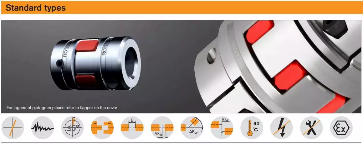
Modifications
The aim of this paper is to investigate the effects of coupling modifications. It shows that such modifications can adversely affect the performance of the coupling mechanism. Moreover, the modifications can be predicted using chemical physics methods. The results presented here are not exhaustive and further research is needed to understand the effects of such coupling modifications.
The modifications to coupling involve nonlinear structural modifications. Four examples of such modifications are presented. Each is illustrated with example applications. Then, the results are verified through experimental and simulated case studies. The proposed methods are applicable to large and complex structures. They are applicable to a variety of engineering systems, including nonlinear systems.
editor by CX 2023-04-13
China Brass Coupling Plumbing Pipe Fittings Brass Screw Compression Fittings for Copper Pipe coupling contractions
Merchandise Description
Transient Introduction:
1. Brass thread fittings
2. Materials: Hpb57-3,59-1,CW602N, DZR,
three. Dimension: 16”, 20”,26”, 32”
four.Developed with brass bar.
five.Leakage test right after finished.
6.Prompt shipping inside thirty times for 1-3 containers.
seven. Samples can be presented.
| After-sales Service: | 24 Hours Online |
|---|---|
| Connection: | Elbow |
| Head Code: | Hexagon |
| Thread Distribution: | Internal Thread |
| Surface: | Nickle |
| Material: | Copper |
###
| Customization: |
Available
|
|---|
| After-sales Service: | 24 Hours Online |
|---|---|
| Connection: | Elbow |
| Head Code: | Hexagon |
| Thread Distribution: | Internal Thread |
| Surface: | Nickle |
| Material: | Copper |
###
| Customization: |
Available
|
|---|
Understanding the Different Types of Couplings
A coupling is a device that joins two rotating shafts together. It transmits power from one to the other and is designed to allow some amount of end-movement and misalignment. It is a simple mechanism that is extremely common in many industries. Learn more about couplings in this article.
Flexible coupling
When choosing the correct flexible coupling for your application, there are several factors to consider. One of the most important factors is backlash, which is the amount of rotational play introduced by moving parts. Other factors to consider include lubrication and accessibility for maintenance. Choosing the right flexible coupling can be challenging, but it is possible to find the right fit for your specific application.
A flexible coupling is an excellent choice for applications that require high alignment accuracy, which is essential for reliable system performance. These couplings can compensate for angular and parallel misalignment, ensuring proper positioning between the driving and driven shafts. In addition, flexible couplings are more affordable than most traditional couplings.
The most common flexible coupling is the elastomeric type, which uses a resilient material to transmit torque. These couplings can be made of plastic or rubber. In either case, they can be relatively lightweight compared to other types of couplings. Elastomeric couplings can also be used for high-speed applications.
Another important factor to consider when selecting the best Flexible Coupling is the pipe you’re connecting. Some couplings are easier to install than others, and some even have tapered edges to make them slide easily on the pipe. Regardless of the choice you make, it’s crucial to remember that proper installation is critical for reliability and safety.
CZPT coupling
An CZPT coupling is a flexible, mechanical coupling that features a high degree of angular misalignment and eccentricity. They are available in different lengths, with MOL being the longest. They are ideal for applications that involve high parallel misalignment, limited assembly access, electrical insulation, and other conditions.
CZPT couplings are a versatile type of coupling, and they are often used to connect parallel shafts. They work by transmitting torque from one to the other using the same speed and rotation mechanism. They are available in various materials, including aluminum, brass, and polymers. In addition, they can work under high temperatures.
One of the main benefits of using an CZPT coupling is the fact that it does not require the use of a gearbox. These couplings are flexible, and their design allows them to cope with misalignment problems that may occur in power transmission applications. They are also able to absorb shock.
Another advantage of CZPT couplings is that they are suitable for systems with low-to-medium amounts of shaft misalignment. Because their friction is limited to the surface of the hubs, they are able to accommodate low bearing loads. CZPT couplings can also be used in systems with limited shaft access, since the disks are easily removed.
Clamped coupling
Clamped couplings are designed to provide a high-strength connection between two objects. A standard coupling has two parts: a nipple and a clamp sleeve. Each part is designed in such a way as to cooperate with each other. The sleeve and clamp are made of rubber. A reinforcing braid is often used to protect the exposed steel braid from rusting.
PIC Design provides a wide variety of standard clamping couplings for many different industries. These include medical, dental, military, laboratory, and precision industrial control equipment. They have a simple design that makes them ideal for these applications. Clamped couplings are also available for custom manufacturing. These couplings are available in metric, inch, and Metric.
The most common type of clamp coupling is a hose clamp. This type of coupling is used to connect two hoses or piping units. It consists of two conical binding sleeves that fit into the ends of the two parts. The coupling is then tightened with a screwdriver. It’s a versatile coupling because it allows two piping units or hoses to be joined together.
Another type of clamp coupling is the two-piece clamp coupling. The two-piece design allows for a quick and easy installation. Unlike other types of couplings, the clamp coupling is not necessary to remove the bearings before installing it. Its keyway is designed with shims in place so that it fits over the shaft. These couplings are available in different sizes, and they are made of steel or dutile iron.
Helicoidal coupling
Helicoidal coupling is a form of nonlinear coupling between two molecules. It occurs when the molecules in a double helix are subjected to oscillations. These oscillations can occur either in the right or left-handed direction. These oscillations are called solitons. Helicoidal coupling can provide quantitative or qualitative support to a structure, such as an electron.
Split Muff coupling
The Split-Muff Coupling market report provides detailed market analysis and key insights. The study covers the market size, segmentation, growth and sales forecast. It also examines key factors driving the market growth and limiting its development. The report also covers current trends and vendor landscapes. Therefore, you can get a deep understanding of the Split-Muff Coupling industry and make the right business decisions.
The report also provides data on the competitive landscape and the latest product and technology innovations. It also provides information on market size, production and income. It also covers the impact of the COVID-19 regulations. The market report is a valuable resource for companies looking to expand their businesses, or to improve existing ones.
In terms of application, Split-Muff Couplings can be used in light to medium duty applications. They are shaped like a semi-cylindrical disc that fits over a shaft. Both parts are threaded for assembly and disassembly. It can be disassembled easily and quickly, and can be used for medium to heavy-duty applications with moderate speeds.
Split Muff couplings are the most popular type of couplings for transferring wet and abrasive materials. Their flanged end fits on most major brands of smooth material muff hoses. In addition, this type of coupling is corrosion-resistant and easy to install. It also does not require any adjustments to the drive shaft’s position.
Flexible beam coupling
The Flexible beam coupling is one of the most popular types of couplings in the industry. It is comprised of two sets of parallel coils separated by a solid member, and it offers a wide range of torsional stiffness. These couplings are made of aluminum alloy or stainless steel. They offer excellent flexibility and are less expensive than many other types of couplings. They also require zero maintenance and can tolerate shaft misalignment.
Beam couplings are categorized into two types: helical and axial. The former is characterized by a high degree of flexibility, while the latter is used to compensate for higher misalignment. Both types are suitable for small torque applications and are available in a wide range of shaft sizes.
Flexible beam couplings are available in metric and US sizes, and feature a variety of options. They feature stainless steel or aluminum materials and are highly durable and corrosion-resistant. They also offer high torque capacities and excellent fatigue resistance. Flexible beam couplings are available with a wide range of options to meet your unique application needs.
editor by czh 2022-12-02
in Tuxtla Gutierrez Mexico sales price shop near me near me shop factory supplier Co Rotating Twin Screw Extruder Machine Parts 10mm – 120 mm Screw Shaft manufacturer best Cost Custom Cheap wholesaler

Maintaining in mind that excellent support is the important to cooperating with clientele, we attempt to fulfill high high quality specifications, supply competitive prices and make certain prompt supply. We are hunting ahead to establishing effective business interactions with new consumers close to the globe in the future. we are self-assured to supply our buyers adaptable and diversified services.
Co Rotating Twin Screw ExtruEPTTEPTT Components 10mm – 120 Mm Screw Shaft
Solution Description:
ZheJiang Advance EPT EPTT,Ltd is devote to deveXiHu (West EPT) Dis.Hu (West EPT) Dis., design, and manufacture co-rotation, counter- rotation pXiHu (West EPT) Dis.Hu (West EPT) Dis.lel twin screw extruEPTTproduction line. we combine and upgrade these activities to EPT our EPTT concept and sort our core EPT quot bilateral EPT symmetrical driving program quot. The EPT allows our extruders have the advantages of quotEPT torque, large performance, low strength-use, higher cost/functionality ratio,EPTT support life. quot We keep rate with the initial class extruEPTTmanufactures in the planet.
And we also manufacture screw segments for twin screw extruEPTTfor Leistritz, APV, Kobe, OMC, Buhler, Kraussmaffei, Theysohn, Buss, Berstorff, Toshiba, Clextral, Labtech, USEON, Coperion, Lantai, JSW, Keya, Maris and so on.
Kinds of shaft :
Solitary keyway
Sq. keyslot
EPT torque key button
Dual keyslot
Involute internal spline
Round keyslot
Retackle spine
EPTT’s needs accessible
Involute spline shaft :
Construction :with cooling method/without cooling h2o
Size:diameter ten-120mm/duration five hundred-9000mm
EPT:
(one)40CrNiMo with EPTT treatment and involute form can be utilised unEPTTthe circumstance of large torque,higher torsion and substantial load.
(2)And nitrogen bearing Matensite stainless steel, WR15E and WR30 can also be applied to make good toughness and EPTT overall performance obtainable. The overall performance parameters comparable to the EPTTed shaft but with a lot more EPT productive, the machining procedure is unEPTTaccurate controlling to make sure the accuracy of groove depth and distance, the smoothness of the floor, toughness and durability as well.
EPT Application :
Ralloy WR15E is a chromium-molybdenum-vanadium-alloyed steel which is characterized by:
– Exceptional tensile strength merged with very good toughness
– EPT thermal balance, higher resistant to thermal EPTs
– Excellent substantial-temperature toughness
– Good machinability and polishability
– Exceptional by means of-hardening qualities
– Very good dimensional security in the course of hardening
Rally WR30 is a higher force nitriding iron-based mostly Cr-Mo alloy which is characterized by :
– Outstanding corrosion resistance
– Excellent machinability
– EPT dimensional stability soon after warmth treatment
– Outstanding grinding and poEPTTng capacity to get optional surface high quality
– EPT longevity by maXiHu (West EPT) Dis.mum hardness unEPTTstatic and dynamic calls for
– Excellent use resistance
– EPT temper resistance up to 500 ordmC
40CrNiMoa is a variety of Alloy constructional metal.

